Electronics
Brought back from the Dead! The Gaggia Baby Dose MAJOR repair
A friend recently bought a ‘new’ coffee machine from eBay for 35 pound. This was a Gaggia Baby Dose which typically, when working sell for between 120-250 pound. When purchased, the seller advertised it as ‘tripping the electrics’ when switched on. This is often caused by a water leak sending current away; so he took a gamble and decided to purchase it with the intent of it being a quick repair.
When it arrived he swiftly dismantled it and indeed found evidence of water leakage, but more worryingly there was evidence of burnt out components on the control board. I am not a fan of coffee machines with control boards. Manual switches controlling individual parts of the machine are far more reliable. Steam and high pressure water, a centimetre or two from mains voltage rarely ends well if there are even the slightest of fault conditions. He brought the machine over to the workshop and we started work on a repair.
The aim of this repair was not to end up spending as much as a working machine. So many of these repairs may beckon the question, ‘why not just buy a new component’, but this defeated the purpose of the project, which was to fix the machine at little to no cost. In fact in total the repair bill totalled parts at less than 15 UK pounds.
Control Board
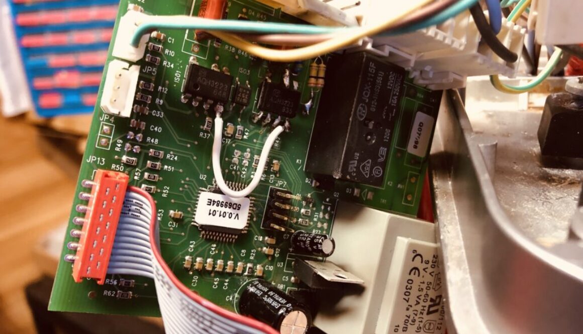
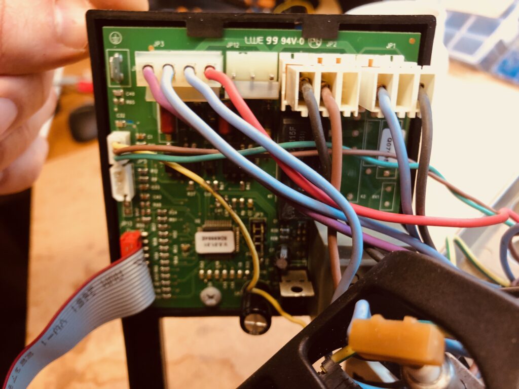
Initially we labelled and dismantled all components to examine their condition. The control board was made up of a low voltage / high voltage separated control board with solid state relays between the two. One controlled the pump/solenoid, and the other controlled the heating element. It was obvious one solid state relay had completely burnt out taking with it the capacitor/resistor network nearby. Several components were either missing or crumbling in smokey remains. By examining a photograph of a replacement board found online we were able to establish the values of the components and order replacements cheaply from eBay.
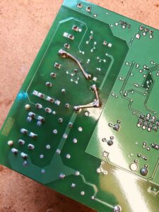
Several components including the Solid State Relay IC and the supporting resistors were changed for 1/4 watt through-hole versions.
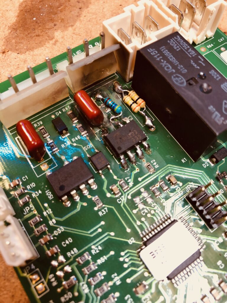
The components were replaced, and the machine fired up. Nothing. Dead as a dodo. Starting systematically with a multimeter, I checked the voltage at the switch which showed voltage at the terminals but one side of the DP switch was not connecting. Removing the switch showed a previous attempt at a repair. A blob of solder had been crudely applied to one side of the connector to try and establish at better connection.
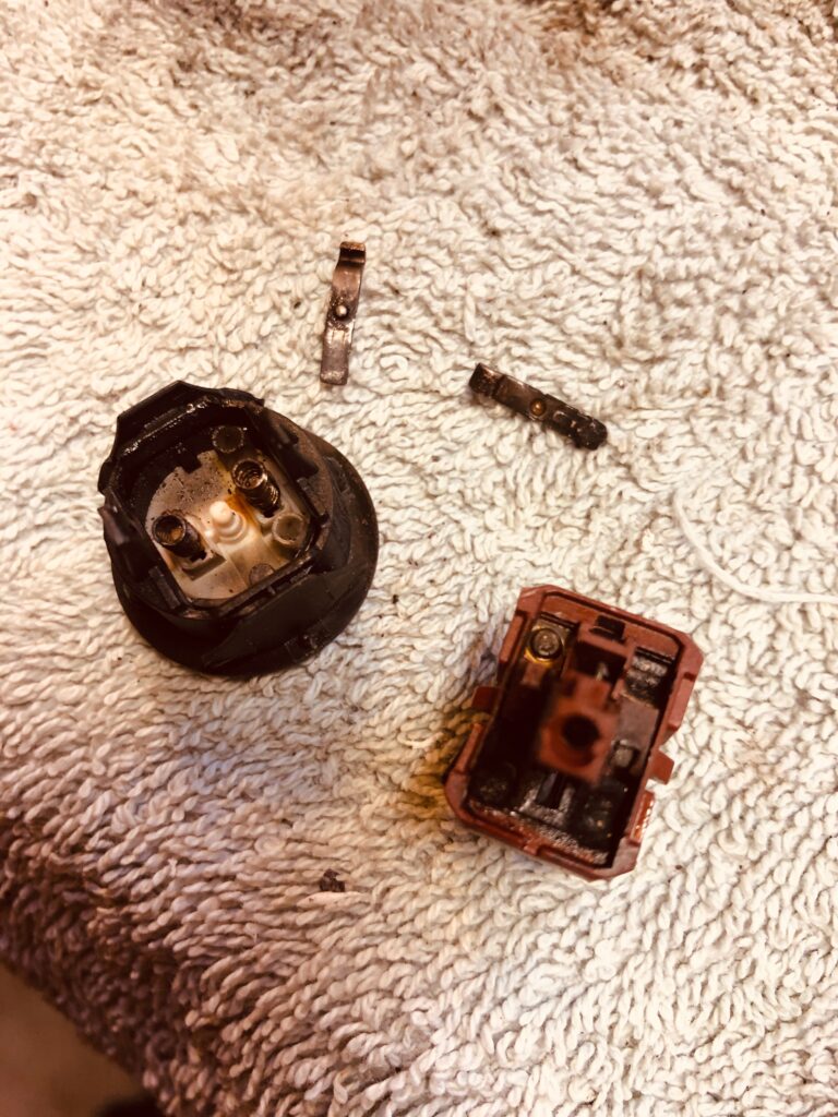
It was clear this switch had called it a day. Fitting a new switch was a little tricky. Replacing the switch with an original part would have been at significant cost, so it was time for some case modifications to install a standard robust DP square switch in a round hole. A bit of gentle work with a hacksaw saw the switch fit in nicely. Sadly the spade connectors did not fit, so off they came and new ones crimped on. We had power to the board! (And a nice light up switch as a bonus!)
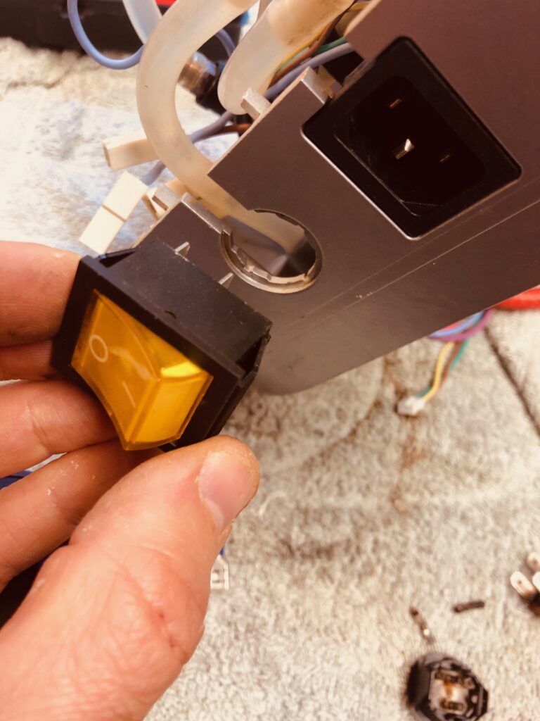
Hm, a problem astronauts have had in the past. 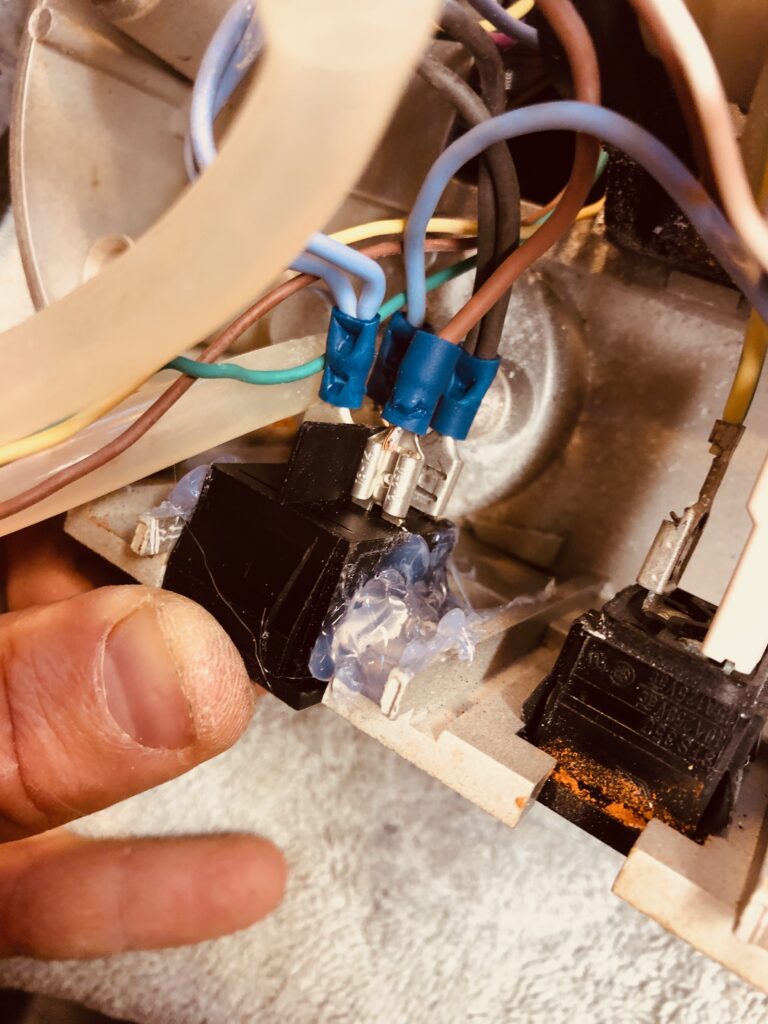
Hot melt glue to secure the switch 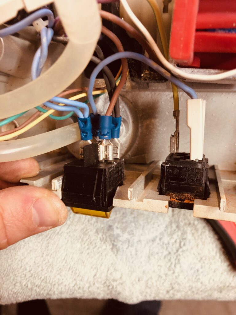

Replaced spade connectors 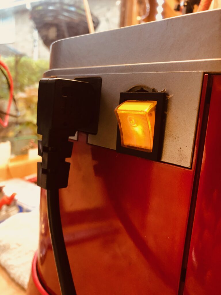
Not perfect, but a working switch for £4!
Power up! We have flashing lights on the front panel. The ‘heating’ lamp was flashing. (More on this later), and the heating elements are heating. Good news so far.
So we filled the tank with water and dare to hit the pump button.
There was noise. Lots of it. And heat! Good signs for coffee, but alas no water fell from the group head. Water did spray all over the inside of the machine however. The steam wand was also functioning okay. So why no water from the grouphead?
First thing to do was strip the boiler apart and see if we have a clear path for the water to run. The boiler was not in good condition, and nor were the rubber seals:
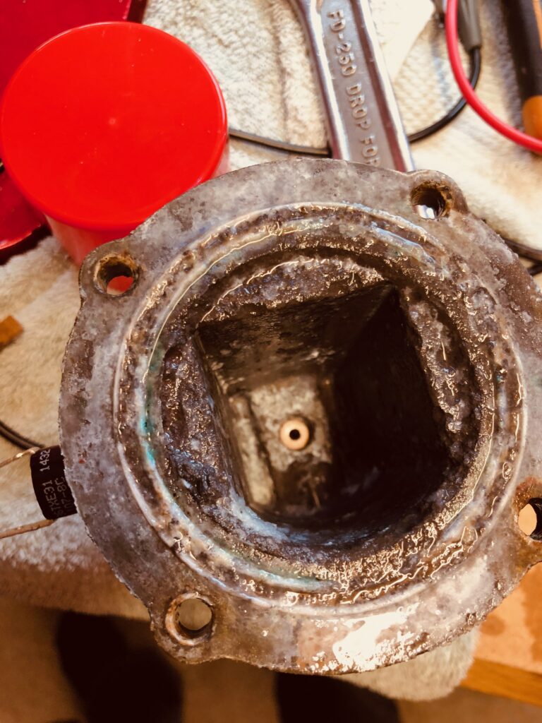
Inside the boiler chamber 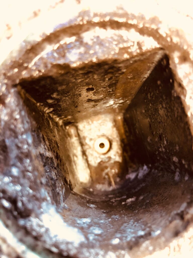
So much corrosion, getting this cleaned up would be difficult 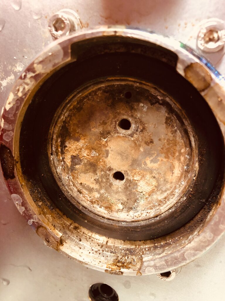
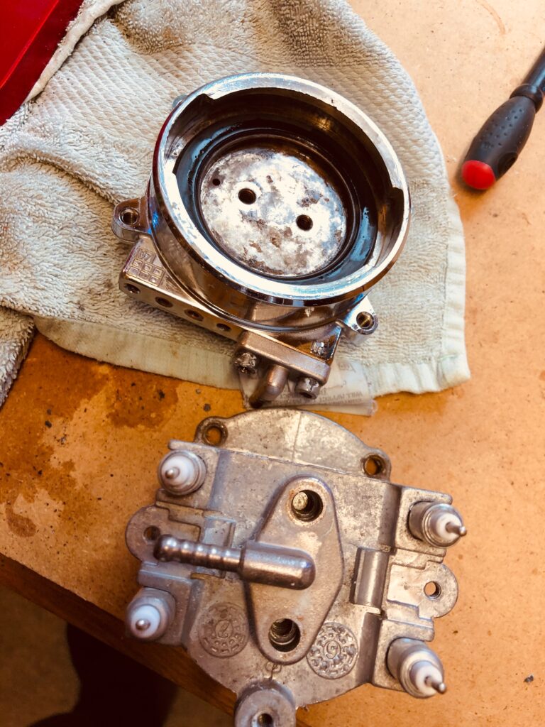
The grouphead before cleaning. 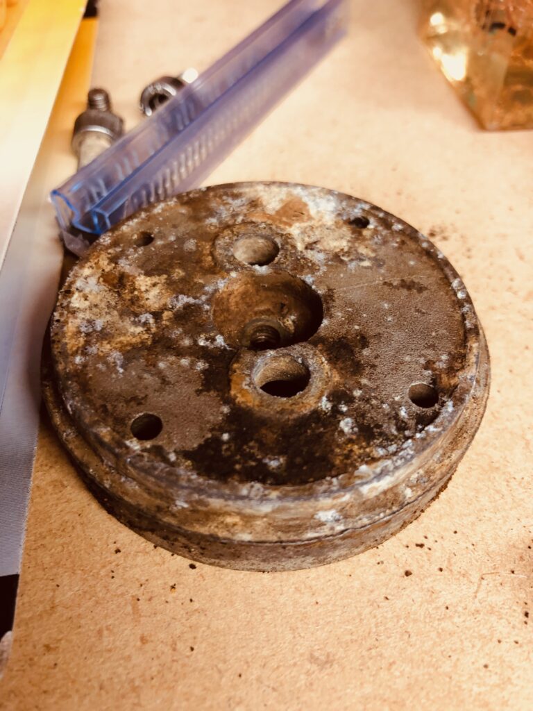
The shower plate corrosion 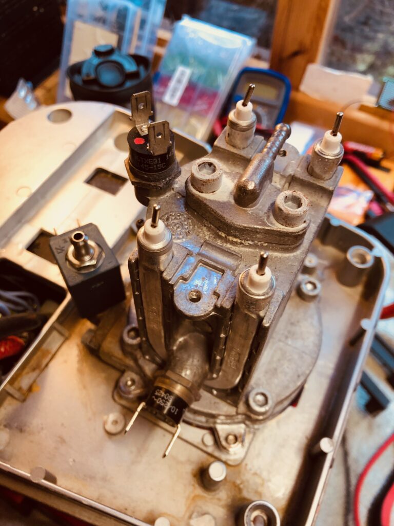
The thermostats appear to work, but are cheap so were replaced anyway.
Shiny grouphead after cleaning 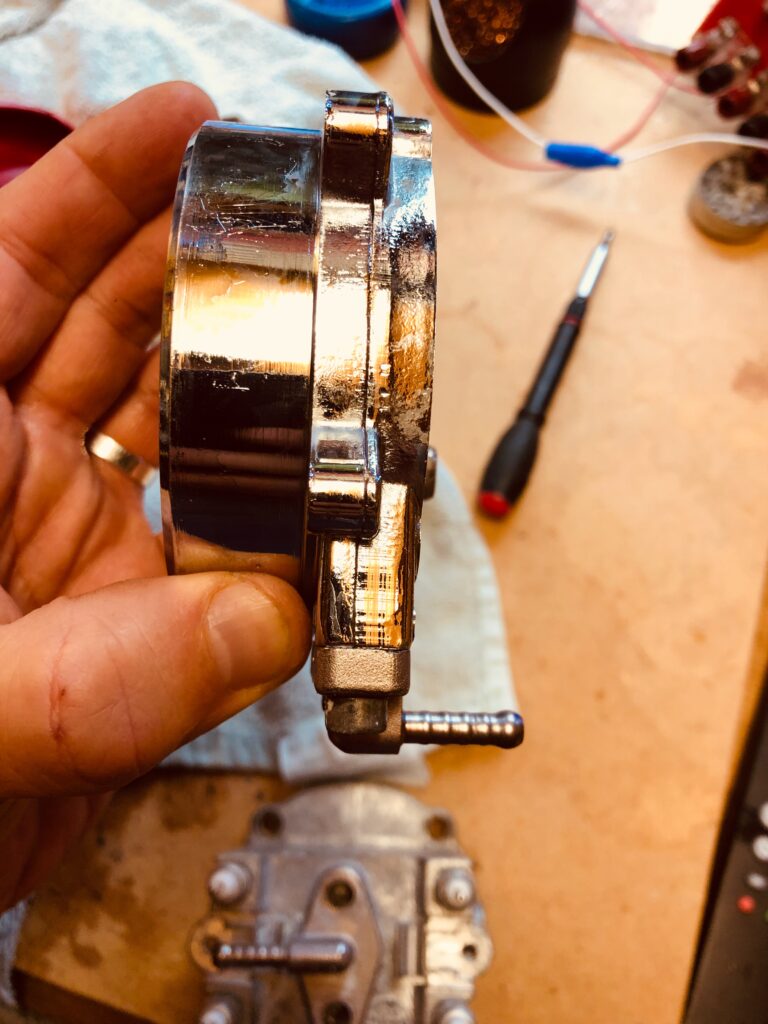
Looking good!
If we follow the waters path from the pump, it enters the bottom of the boiler via a rubber tube. This then fills the boiler until the water reaches the top of standing copper pipe that’s purpose is to stop the boiler running dry.
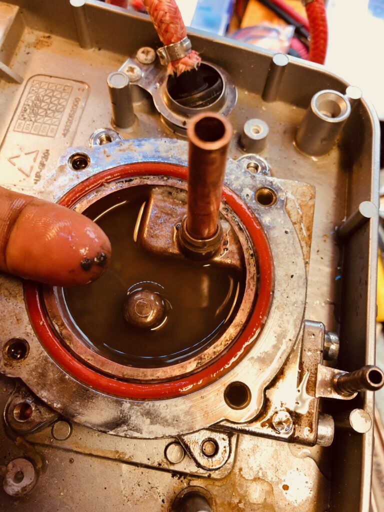
Once the water runs down this pipe it exits the boiler via a small tube and usually immediately reenters the grouphead directly below. This function is permitted via the use of a solenoid. The solenoid is a small diverting device controlled by a coil which is powered by the control board. Without power to the coil the path of the water is permanently blocked to the grouphead.
What is the purpose of the solenoid? Well at the end of your coffee shot the solenoid opens to create a third path for the water to exit up through the top of the solenoid tube via a tube back to the drip tray. This function allows the ‘puck’ of coffee to be dry after you have pulled a shot. This convenience stops the puck being soaked in water, but is largely a nicety we can do without. Many machines, including the later famous Gaggia Classic removed this feature entirely, and for the sake of convenience we too are going to remove it.
So we move on to the long and arduous process of removing the coil from the circuit entirely. This proved to be quite a lot more work than I anticipated.
Removing the solenoid we see its in a pretty bad way:
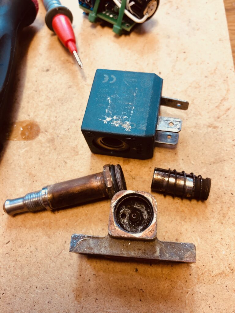
Testing the coil itself shows open circuit. I suspect what ever blew the circuit board also caused the coil to see a large current and act as a fuse. Replacing the coil is a substantial cost even for a used part, and on closer inspection the coil cylinder tube it encapsulates was also cracked. Bad news all round, but none the less we cleaned it all up.
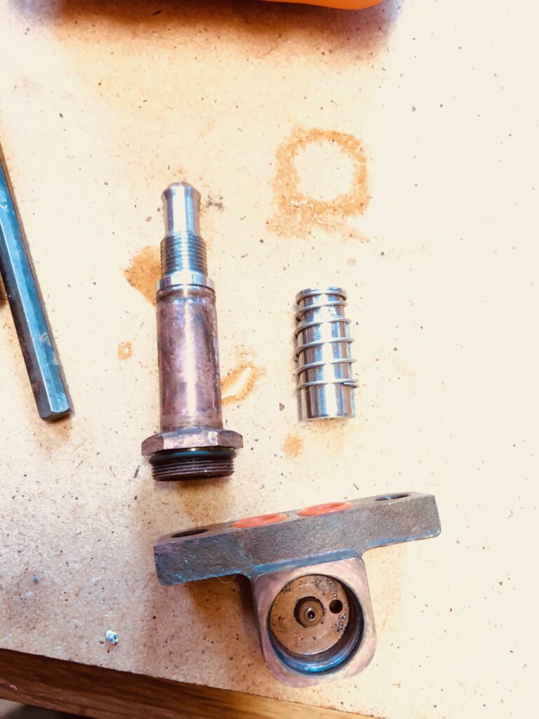
The bottom component above that attaches to the boiler has two holes. The hole on the right side and the centre hole. The water would come up one hole and ideally go back down the the adjacent hole. However this depends on us blocking off the solenoid tube above that allows water to flow back to the drip tray through the now cracked tube.
The problem is this water is pressured at 15 BAR and is not going to be stopped easily. Particularly with a crack in the tube. So what do we do ? It turns out we needed 3 attempts.
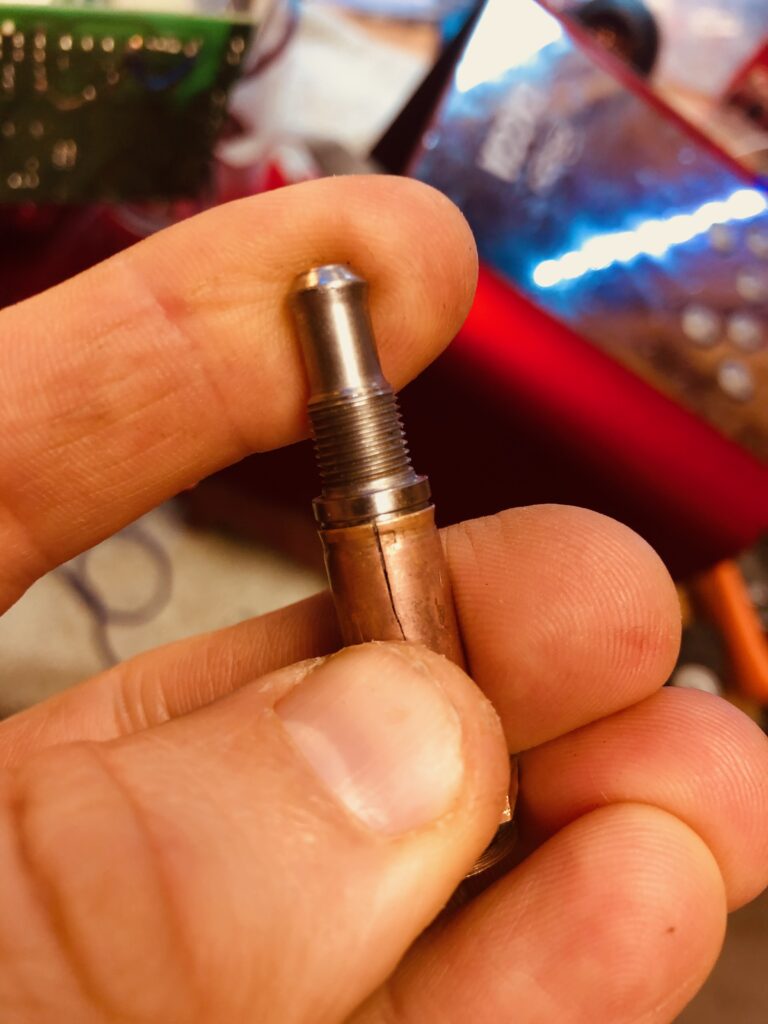
Firstly we tried filling the tube with sealant. This was optimistic and as suspected the sheer pressure of the water forced the sealant both up the tube to the drip tray and through the grouphead. Knife through butter.
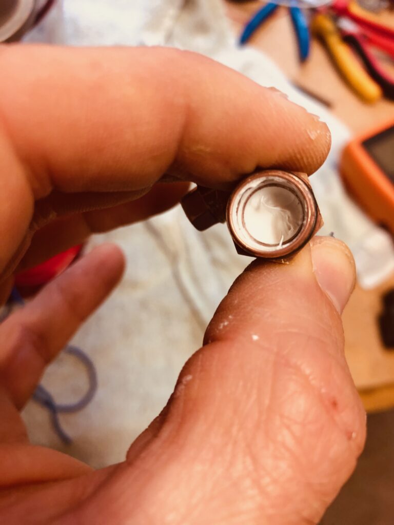
We needed something stronger: Much stronger.
Next was synthetic rubber cork. This was shaped to fit the solenoid tube and forced down the tube entirely blocking the exit. I was confident this would work, and indeed it did. For about 15 minutes. The force of the water stripped the cork into pieces and forced small fragments of it through the grouphead, blocking the internal small pipes in the grouphead itself. This was a major problem and I feared may spell an end to any further attempt at fixing the unit. Even if the water was flowing correctly through the modified solenoid valve, it was now restricted in the grouphead itself which has no easy access.
However, using small pins, and a lot of patience, I was able to extract the small pieces of cork, and there was much relief to see a high force jet of water being emitted from the grouphead, along with several lumps of cork. Even if it was also accompanied by water shooting from the top of the solenoid valve!
With a cracked tube and no easy way of blocking off the tube, I was losing hope we could repair the solenoid valve without replacing the entire part for around £55. However one final attempt involved using Poundland 2 part epoxy. I filled the tube carefully and allowed it to set for 24 hours. Then drilled the top of the epoxy smooth allowing just enough space for the water to move freely from one port to the next without entering the solenoid tube. Success !
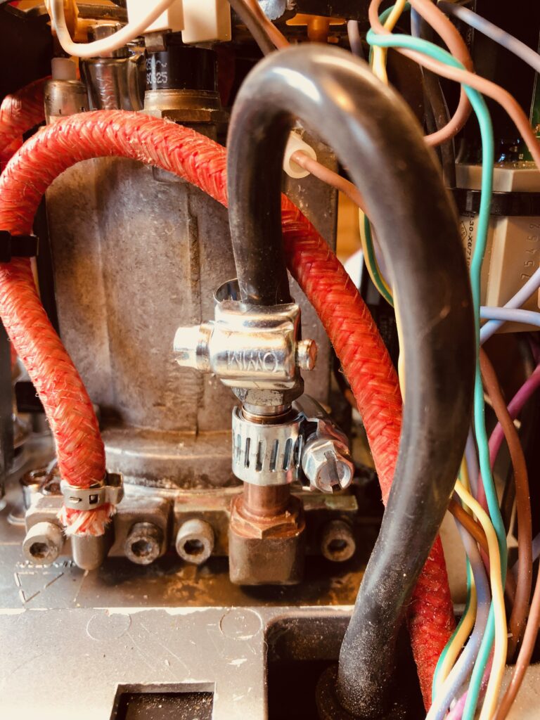
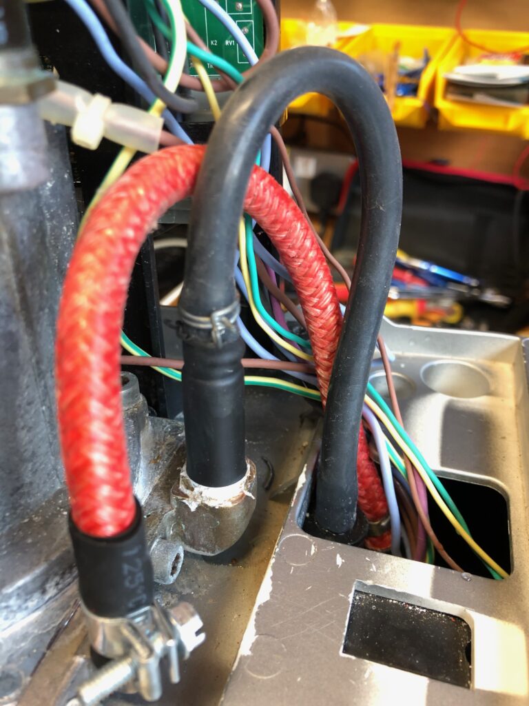
We now had water from the grouphead, but sadly a LOT of leaks. Most of the pipe connections were worn out or were not adequately sealed using jubilee clips when subjected to enormous pressure. Jubilee clips tend to seal with a slight oval shape when tightened, and under pressure this allowed an escape of fluid. We replaced all of the connections with side screw Fuel Hose clips and reinforced the tube seatings with rubber and sealed the joints with PTFE tape. Did it still leak after all this? Yes it did. But only a very small dribble. We can live with it, and the tiny few drops will find their way to the drain holes fine.
Video: Testing the seals.



Its been an adventure, but we finally fixed it. It’s fair to say this machine has its share of quirks and will never run like new, but it creates very good coffee and for just £35, its a bargain. 🙂 Thanks for reading. x
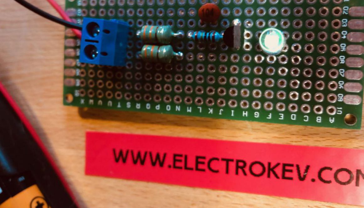
Everlasting ‘Flashing!’ Light
A light that will shine from the moment you are born until you are 18? One single AA battery? Not possible?
The Everlasting light is powerered using the circuit commonly known as the JouleThief. The Joule Thief came to fruition in 1999 when an article by Z. Kapernik was published in the November edition of ‘Everyday Practical Electronics’. Written for the ‘Ingenuity Unlimited’ section of the magazine, the circuit describes a clever little design that utilises almost all of a battery cell. The term ‘Joule Thief’ was coined by Clive Mitchell or BigClive as he is known on his very popular YouTube channel. This is a great channel and I highly recommend it if you enjoy electronics.
Whereas a 1.5 volt battery might be considered ‘Used’ when the voltage drops from 1.5v to maybe 0.9v at best, the Joule Thief carries on functioning right down to around 0.3v. Some advanced versions of the circuit can even drive the cell down to 0.1v.
The following circuit is a modified but simple build of the Joule Thief using Axial coils rather than a traditional wound coil. This makes it very simple for those new to electronics. One of the few difficulties building a Joule Thief is ensuring the coils are wound the correct way. With Axial coils this is not an issue; and so long as the coils are placed side by side, the circuit will work.
There is a wealth of information online regarding the Joule Thief and how it works, but in essence this device is a ‘Blocking Oscillator’ that switches the transistor on and off many thousands of times per second. The coils work together to create a voltage booster, which when paired with an LED appear to show a solidly lit light.
Ordinarily the value of the resistor feeding the base of the transistor would dictate how ‘hard’ the transistor was driven. Often a 1K resistor is used and this will provide a very bright light. In this example, a 10 MegaOhm resistor is used alongside a capacitor to extend the battery life exponentially at the expense of brightness. It’s fair to say the light produced will not light the room, but this project is not about brightness; its about endurance!
The circuit draws just under 13 microamps of power. Considering an AA battery may typically store 2 Million microamp hours of power, this would theoretically drive the LED for 153,846 hours, or 17.56 years. Of course this is very misleading. The battery data sheets that provide this information assume certain power draw characteristics that are more typical than such a low current. It is also quite possible that after 18 years the natural degradation of the battery would see more power loss than the LED load itself. Furthermore, unless extremely high quality batteries were used, its quite possibly the battery would simply leak in that timespan.
But theoretical numbers are what Joule Thieves are all about, and so with that in mind, the project creates a light that will light for almost 18 years. We hope!
This circuit uses simple parts. A single AA battery, and a common NPN transistor. The BC337. LED colours have diferent current draw characteristics, and a green colour has been chosen in this project for its immense efficiency at a low current. The circuit is highly modifiable. Adjustments to the resistor, the inductors, or the capacitor will see different output voltages, light level and longevity.
Keeping the inductors pressed close together will result in a fast flashing light. Creating a tiny gap will speed the flash rate up so fast it will appear as though the light is constantly on.
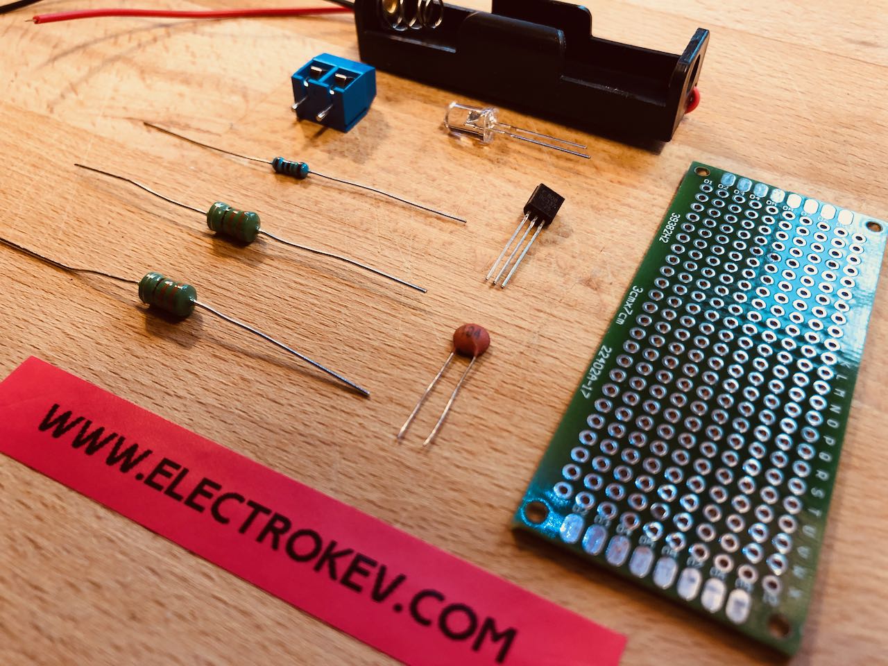

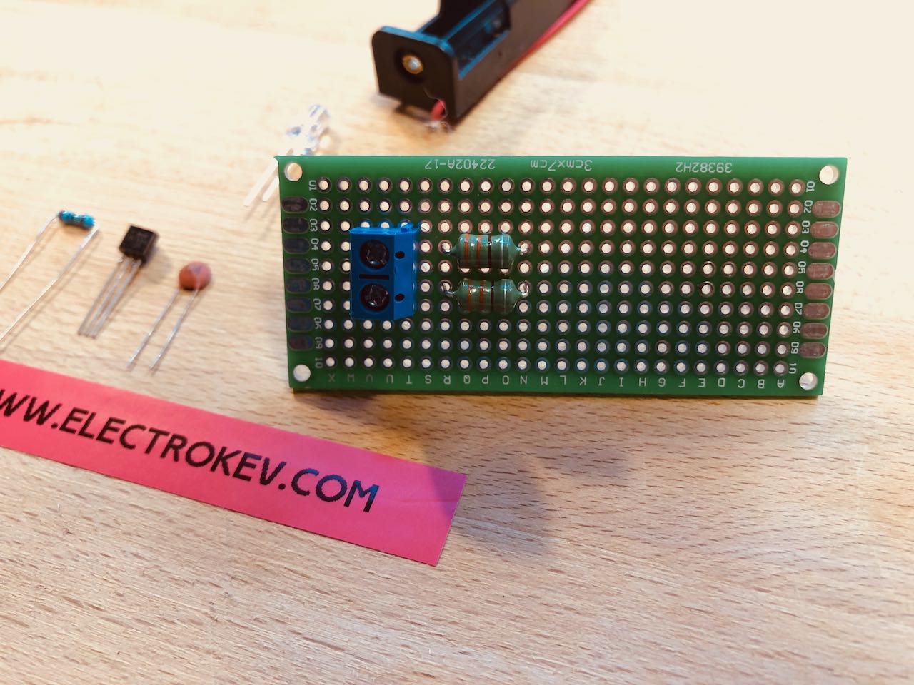
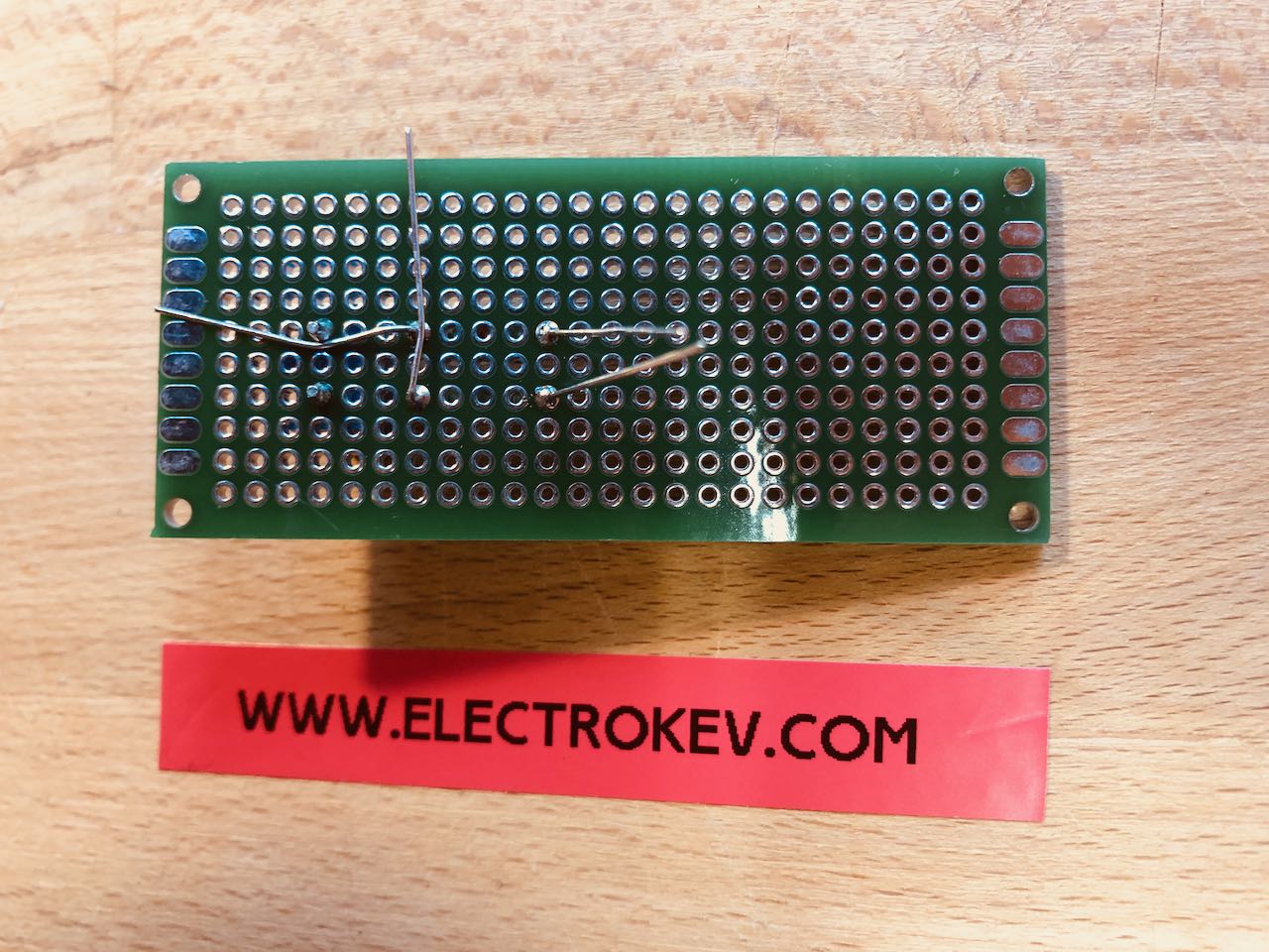
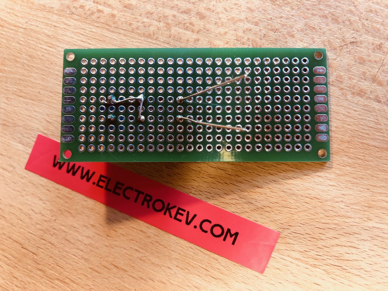
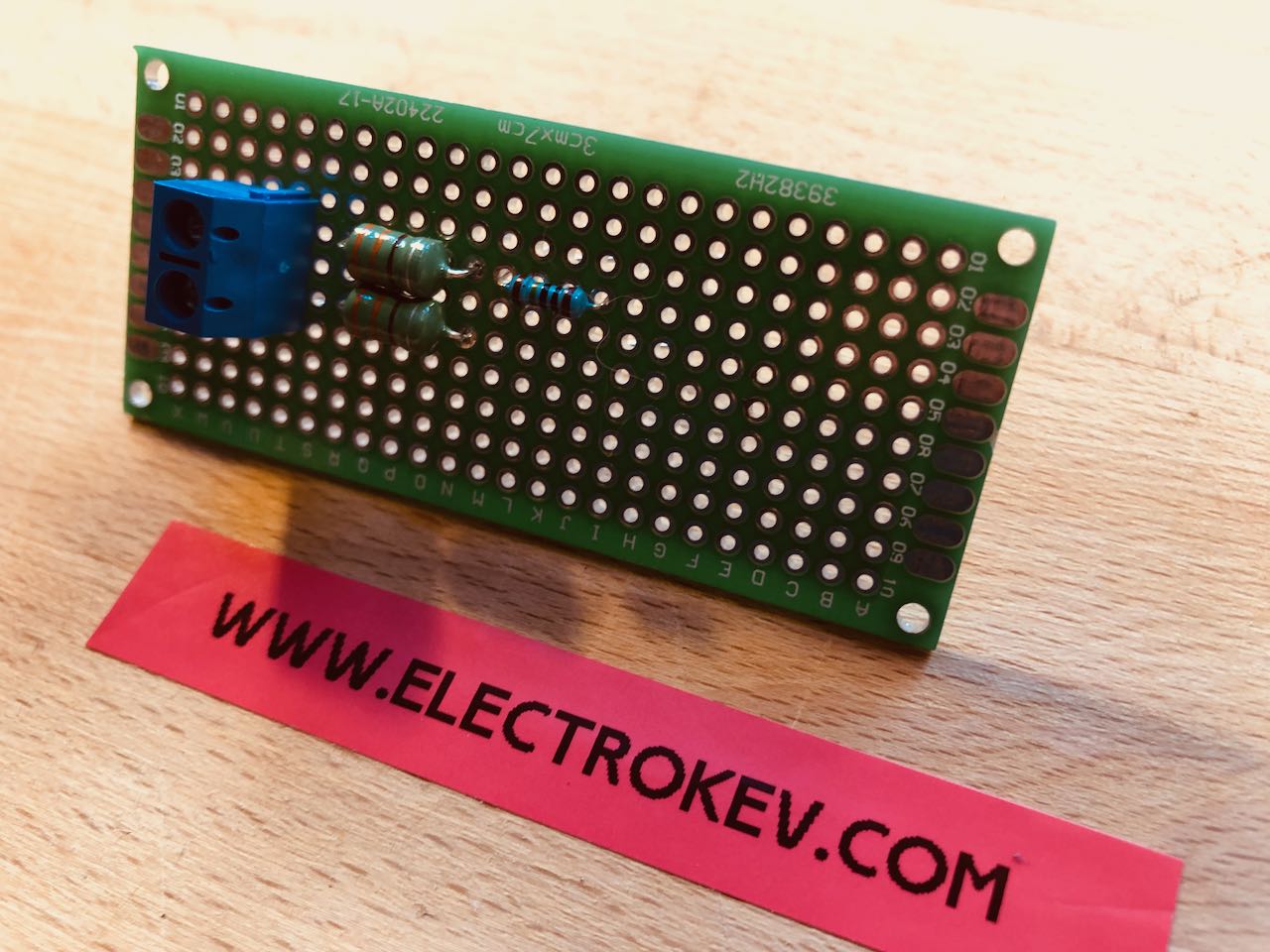

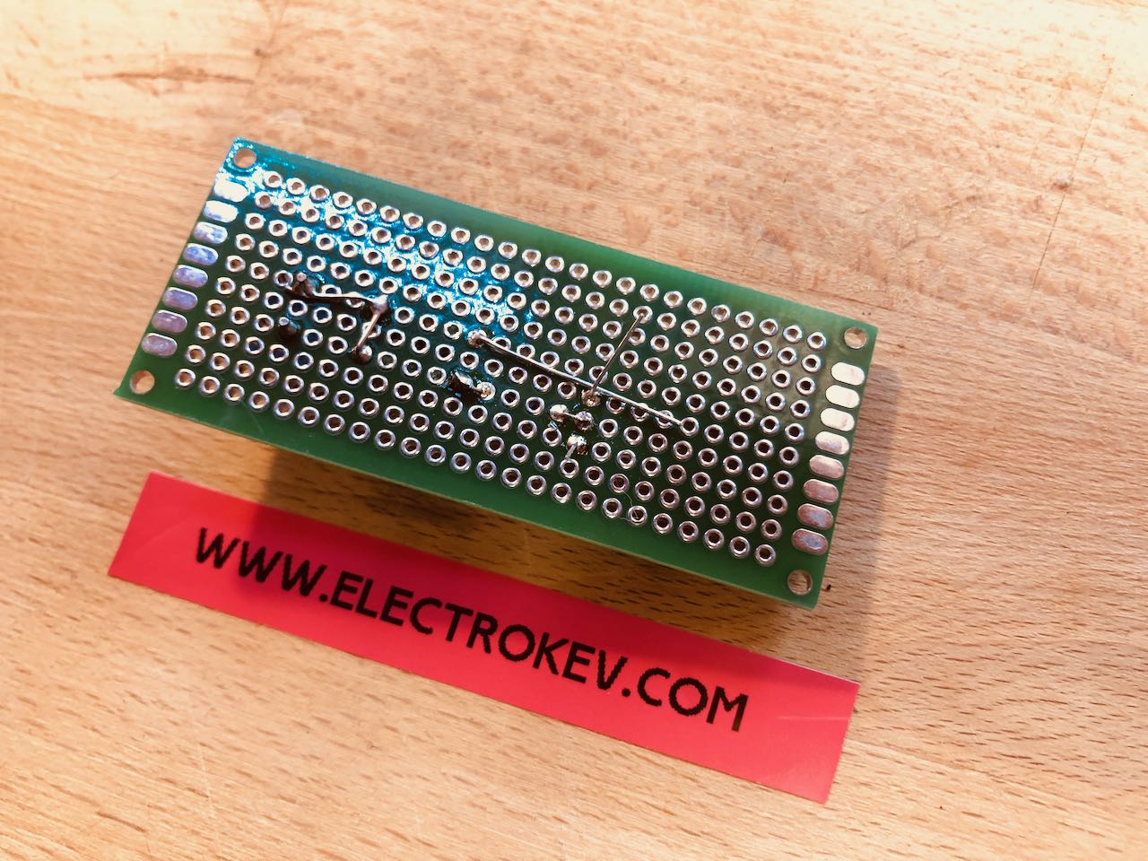
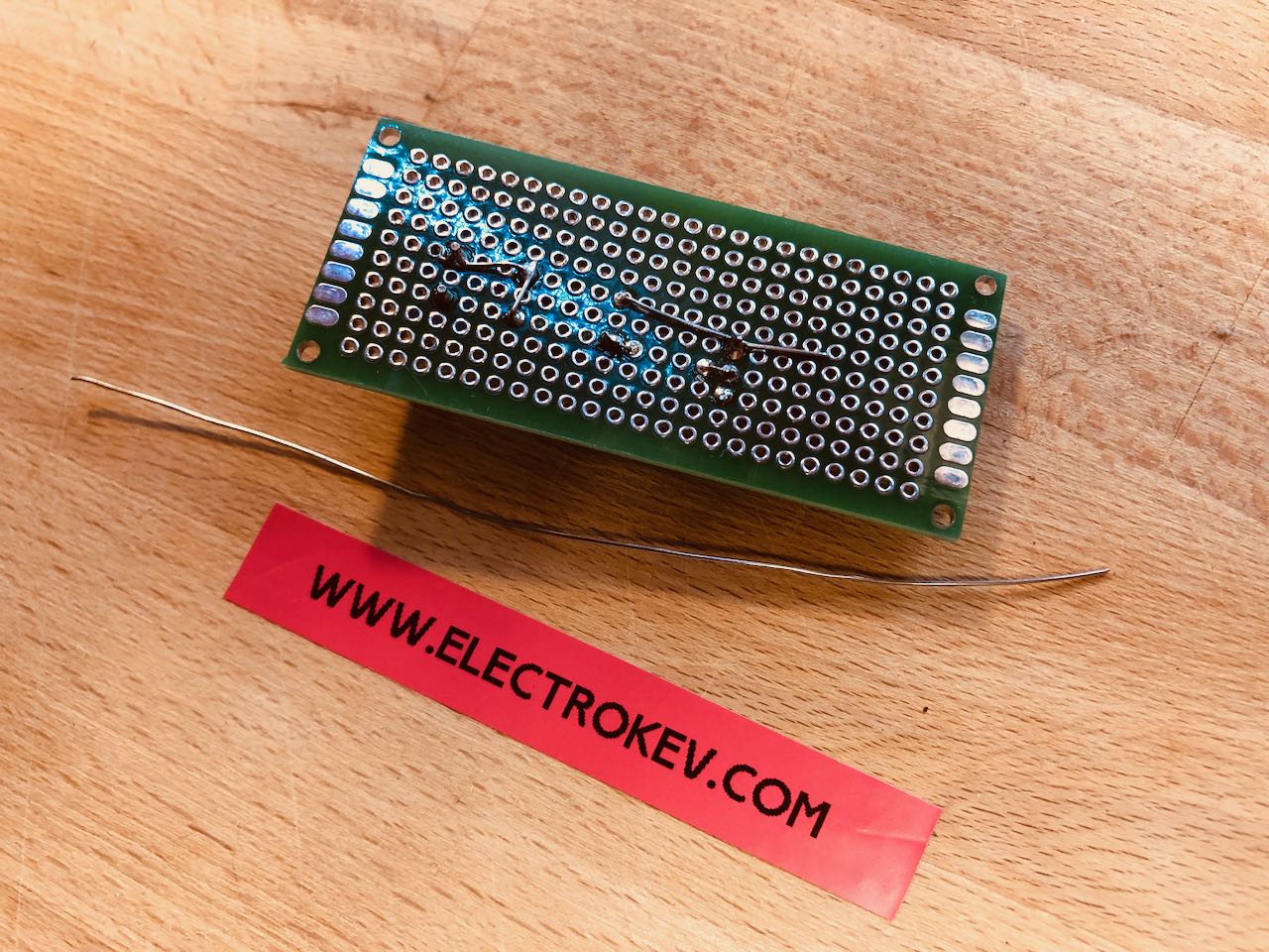
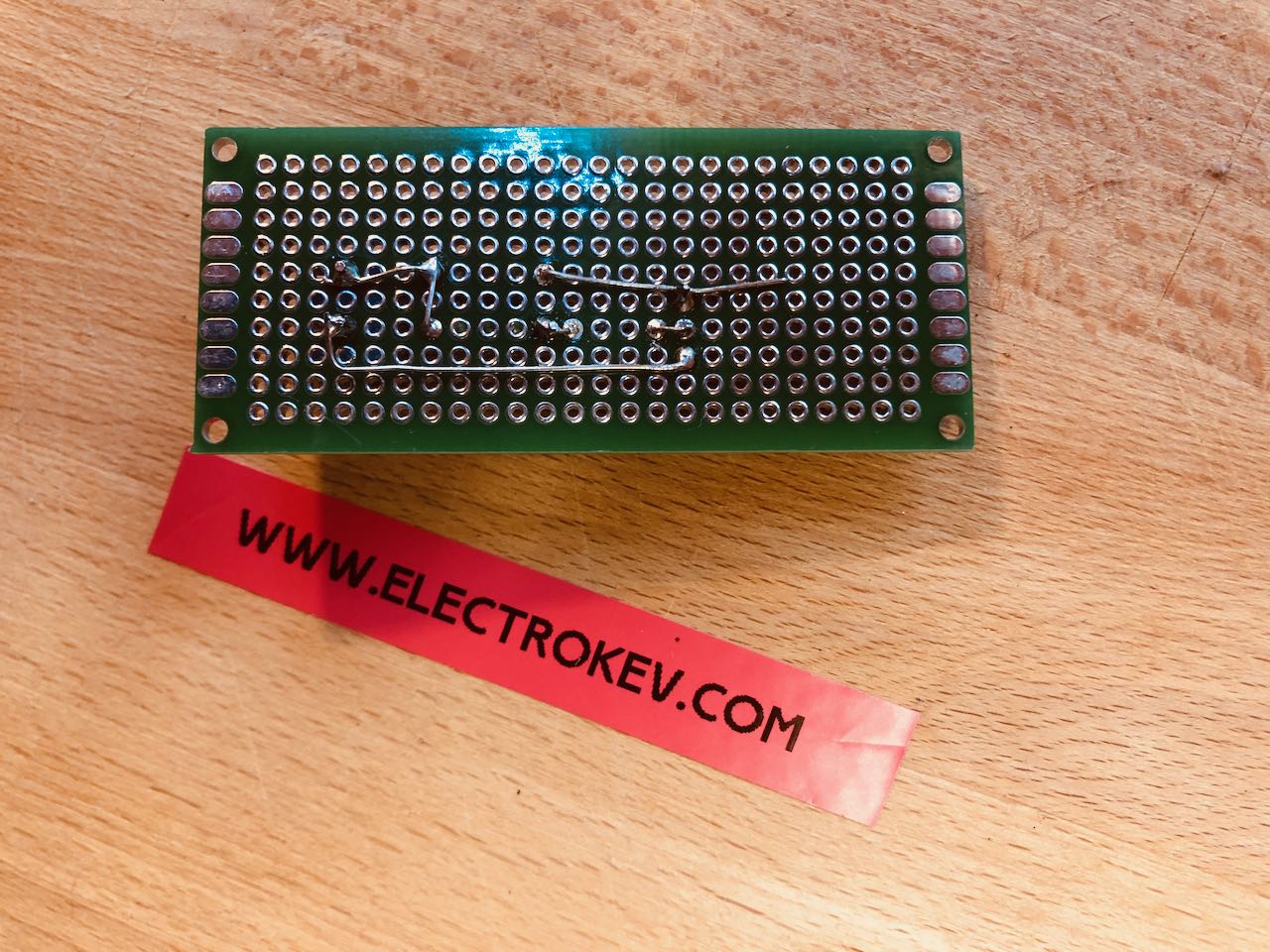
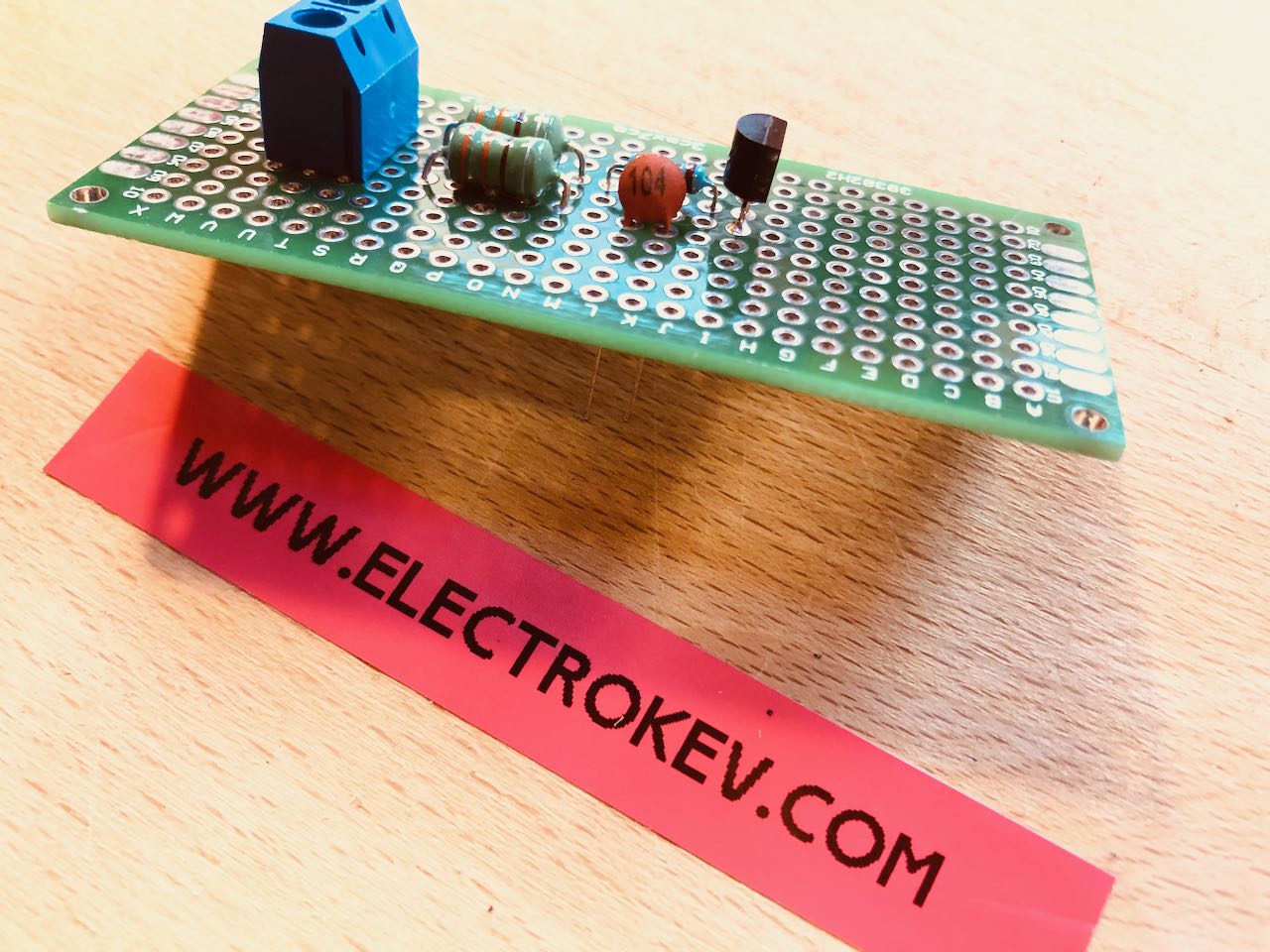
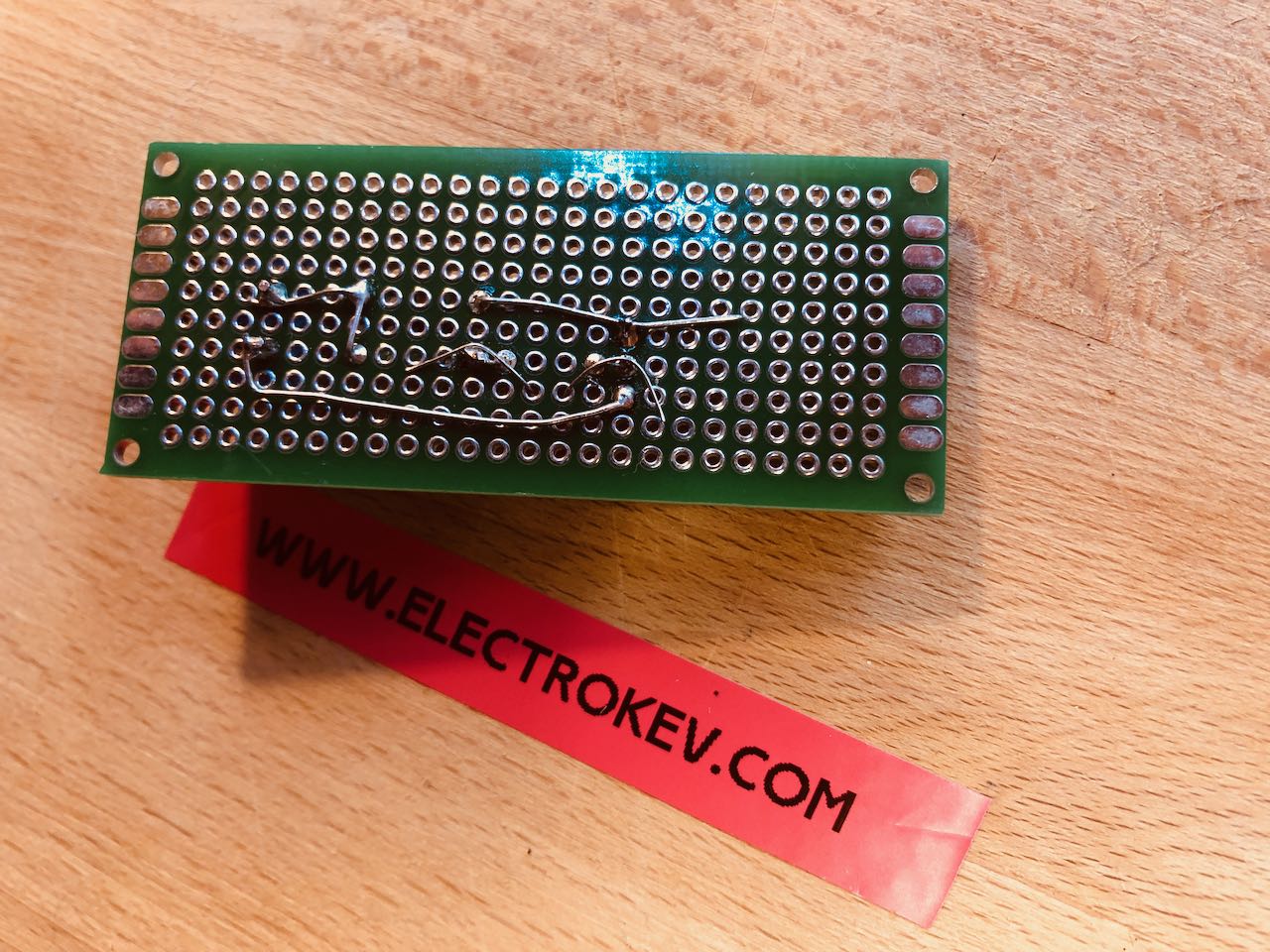
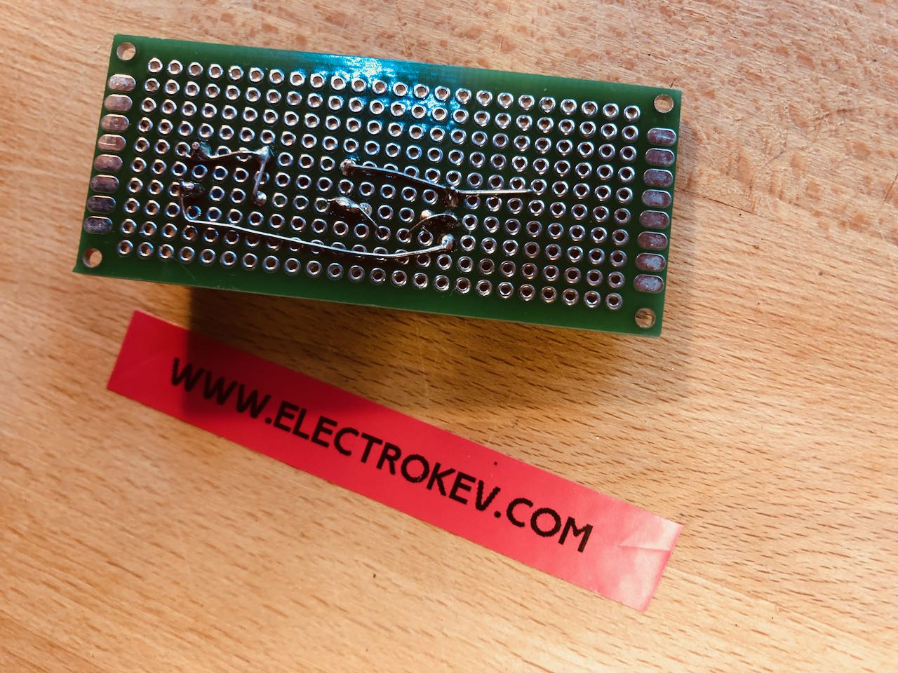

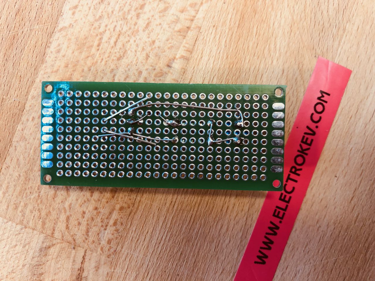

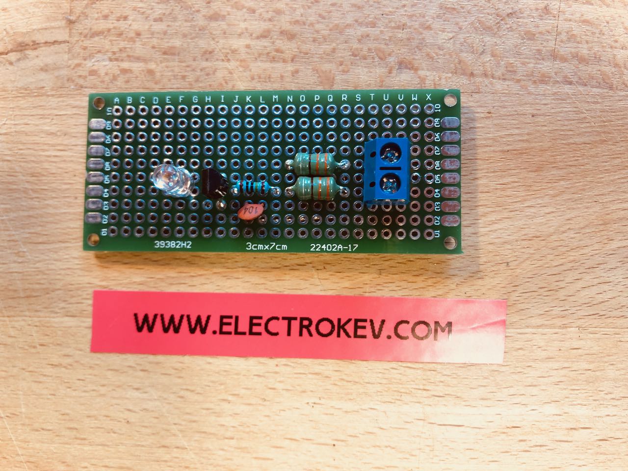
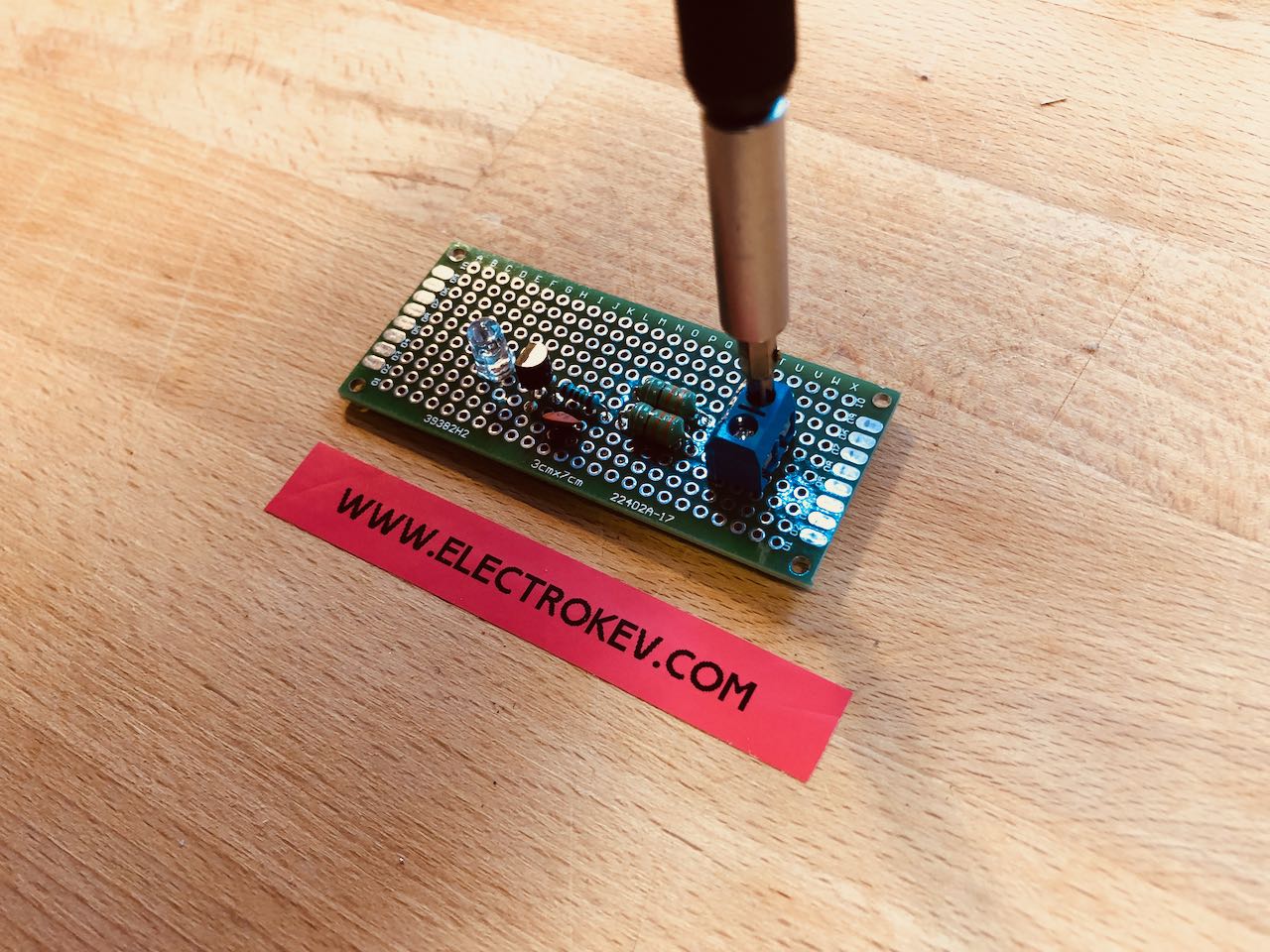
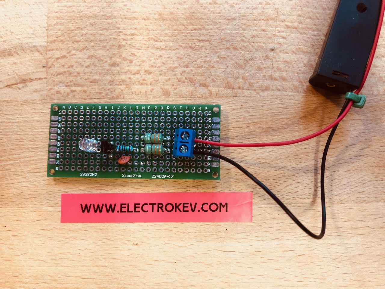
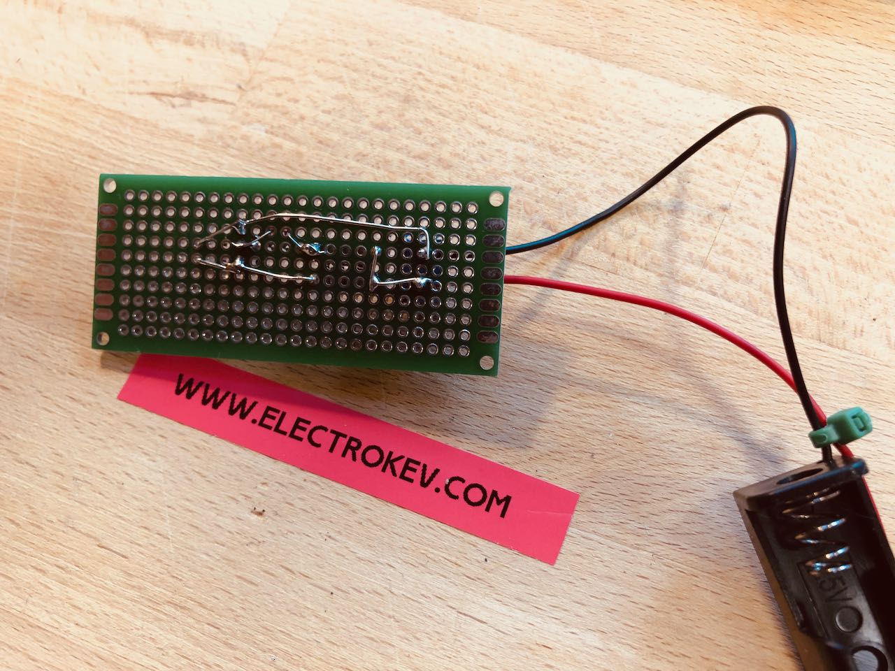

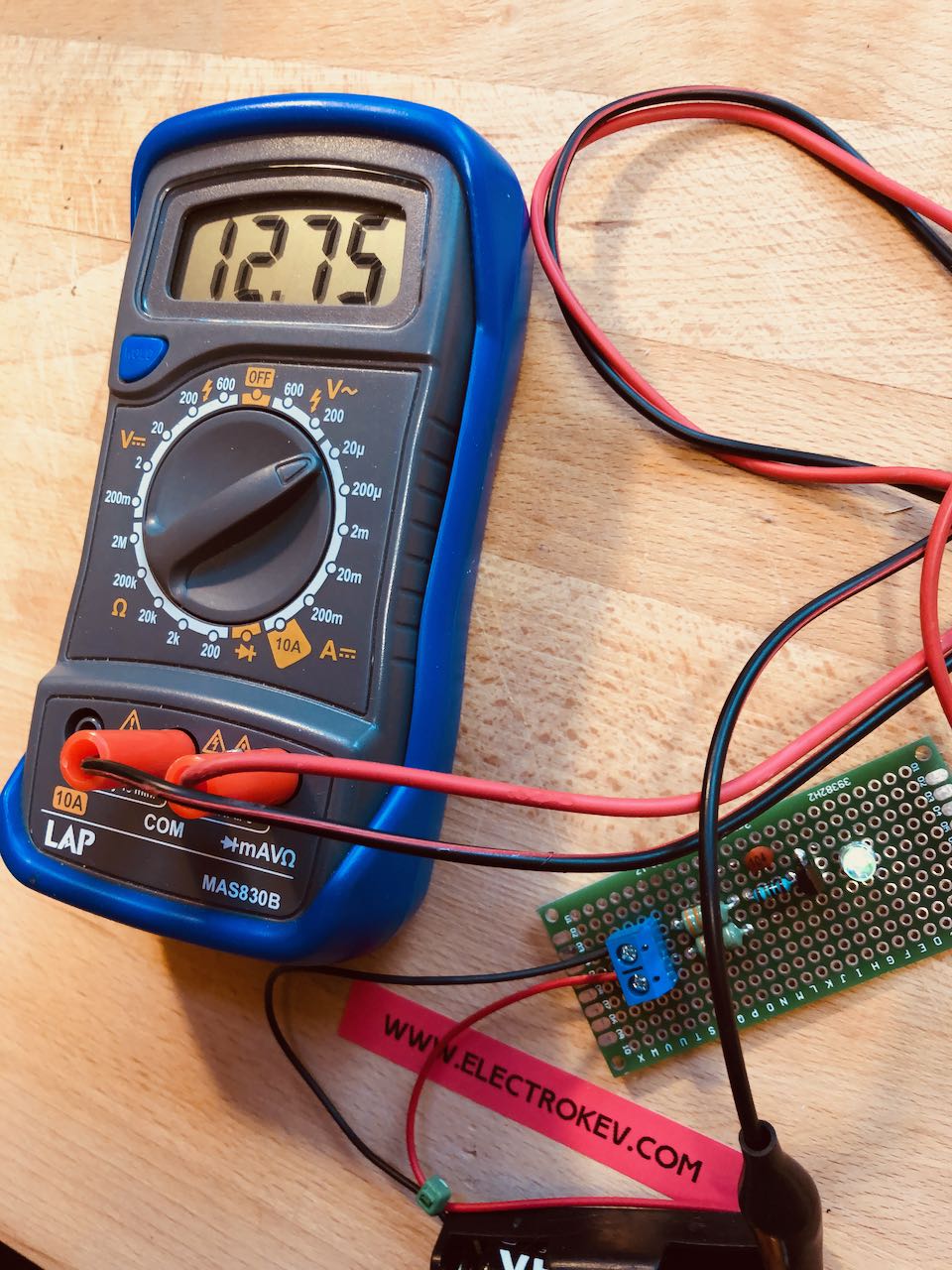
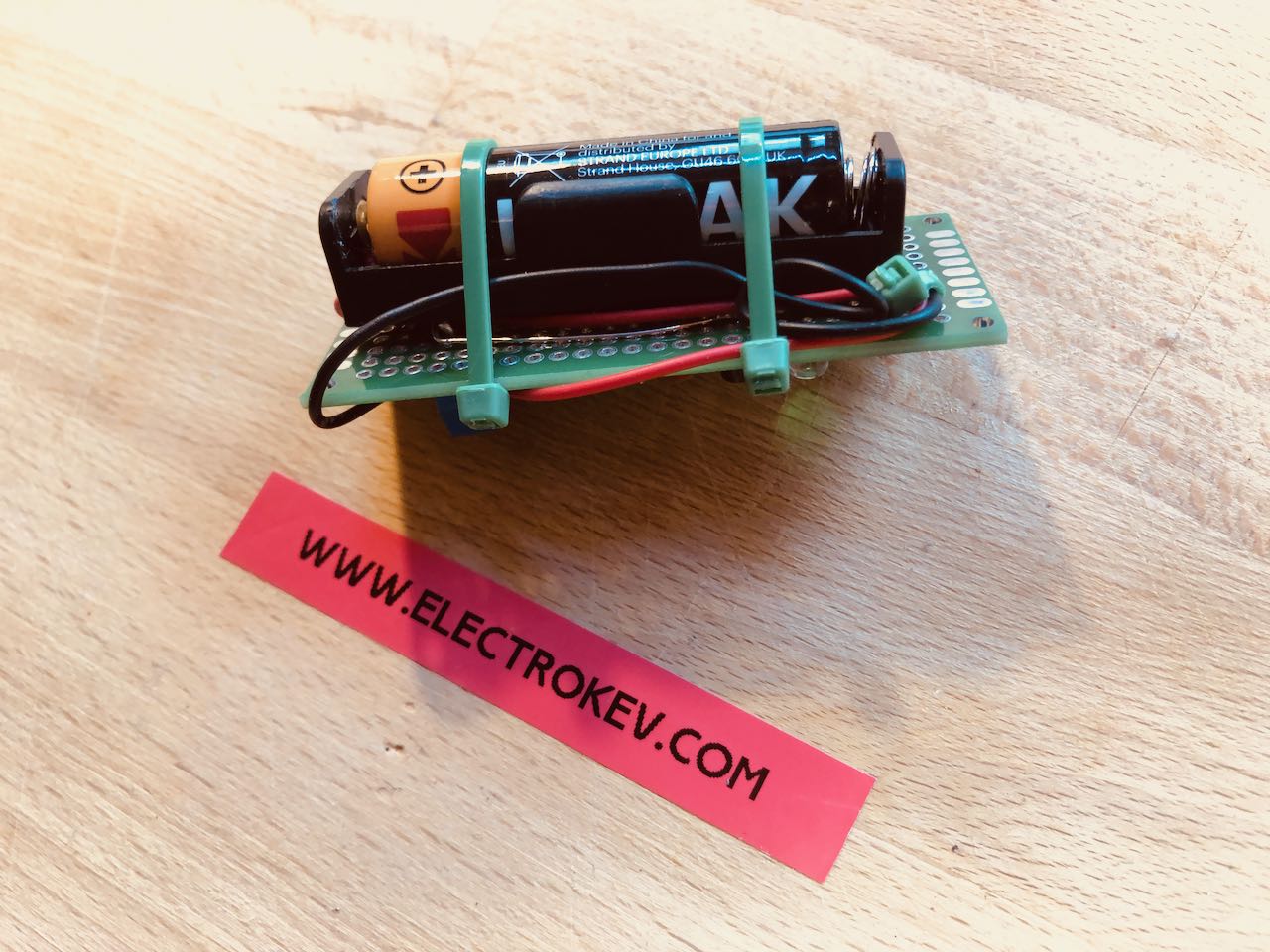
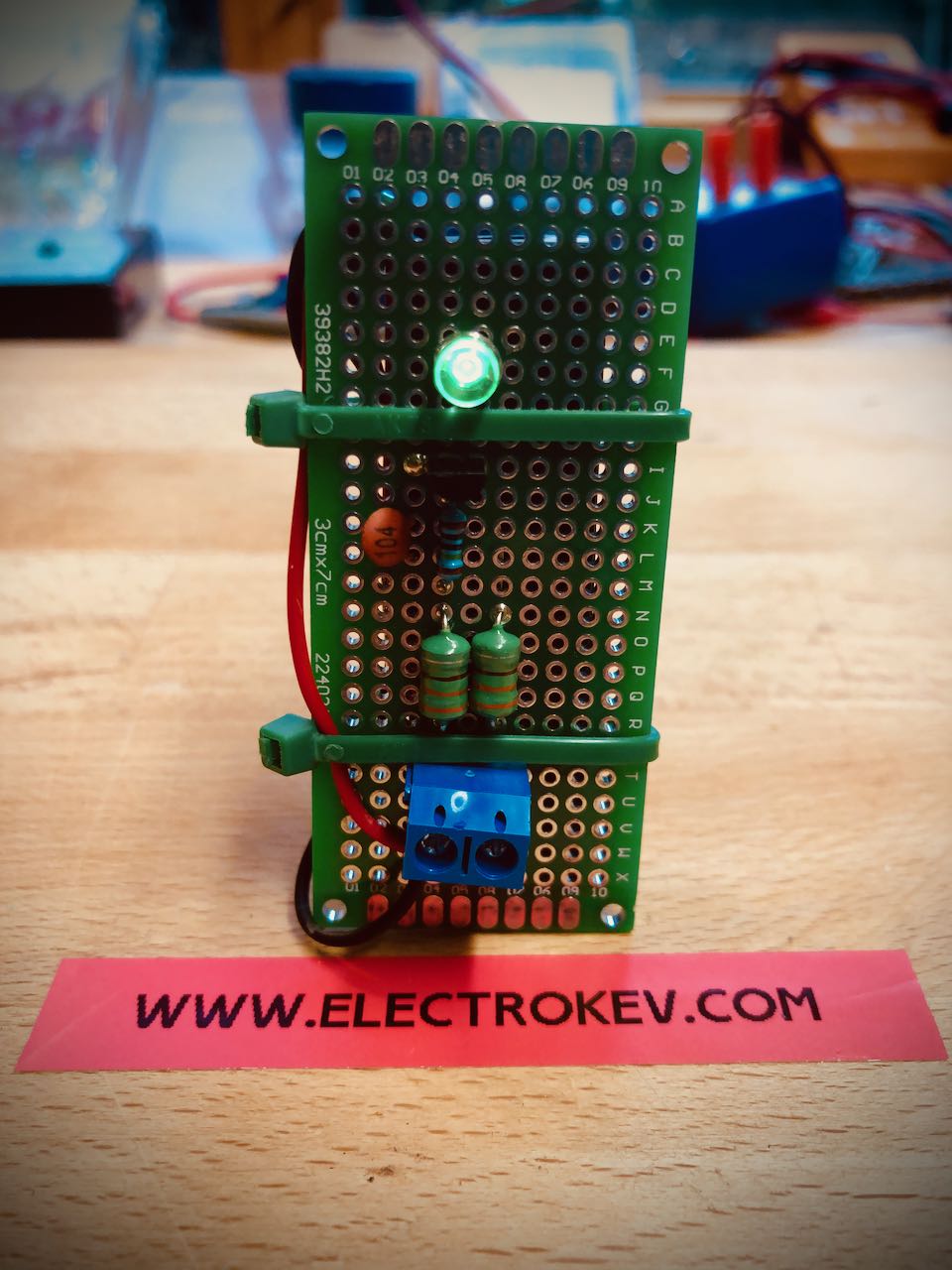
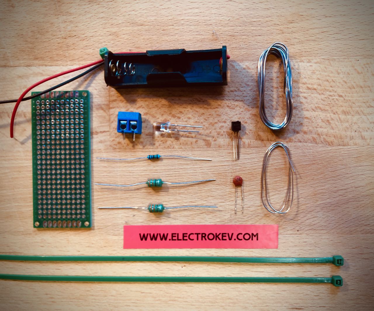
This project is now available to buy in the Shop as a Kit.
All components supplied, including solder and instructions. All you need is a cheap soldering iron, some time and a small space to build. Have fun 🙂

Jacobs Ladder
DO NOT ATTEMPT TO REPRODUCE ANYTHING IN THIS ARTICLE. DANGER OF DEATH. HIGHLY DANGEROUS PROJECT.
Project of the month: Build a high voltage device that will arc bolts of electrical discharge from one electrode to another. This arc should rise up to the top of the device and dissipate before another generates itself at the bottom!
How will it work:
Something like this: a large heavy duty transformer will create 29 volts of direct current at a high ampage.
This relatively low voltage will be fed to a ZVS switch. A Zero Voltage Switch. A ZVS switch will convert the direct current into a high frequency switching DC voltage more suitable for the next stage. The Flyback Coil.
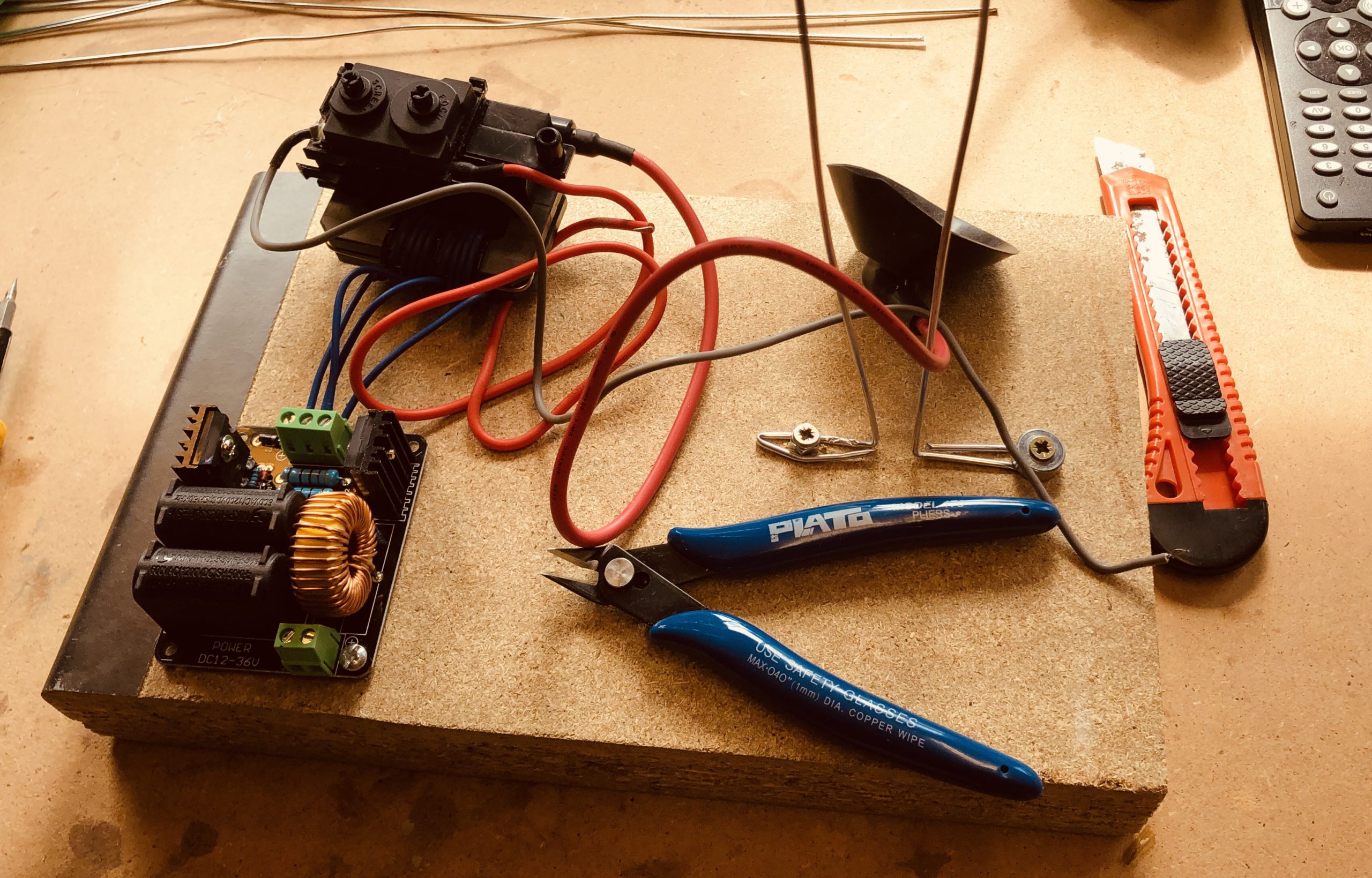
For the coil we are using a FlyBack transformer; the type found in old CRT television sets. This will take the input voltage and scale it up around 1000 times producing a staggeringly high voltage. Many thousands of volts.
This voltage is fed by cable to two large vertical electrodes. The energy potential between them is sufficiently high that a spark will arc from one electrode to the other.
This will occur at the base of the unit as this is where the electrodes are closest together.
As the spark generates enormous heat the spark will start to rise. As it gets hotter and hotter it will rise and rise pulling the gap necessary to leap larger and larger. As the spark reaches the top of the electrode it disappears off the top. Then the process starts all over again.
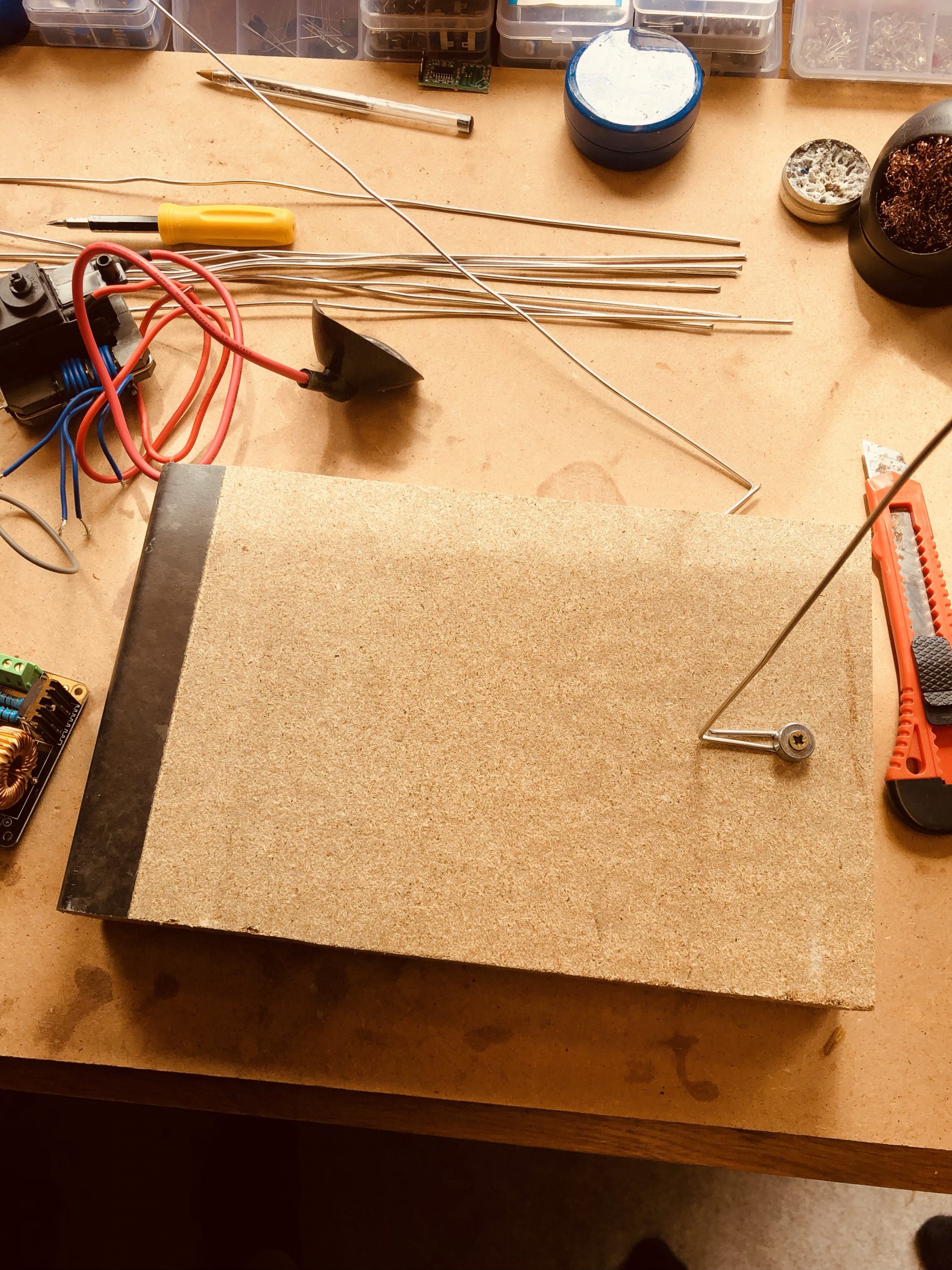
My brother and I started by creating the projects base. The main electrodes used were braising rods, which we would later find out were not the best idea. These rods are soft metal, with a relatively low melting point. As it turns out the Jacobs ladder makes everything it touches extremely hot and consequently the rods did some melting when the arc didn’t rise as expected.
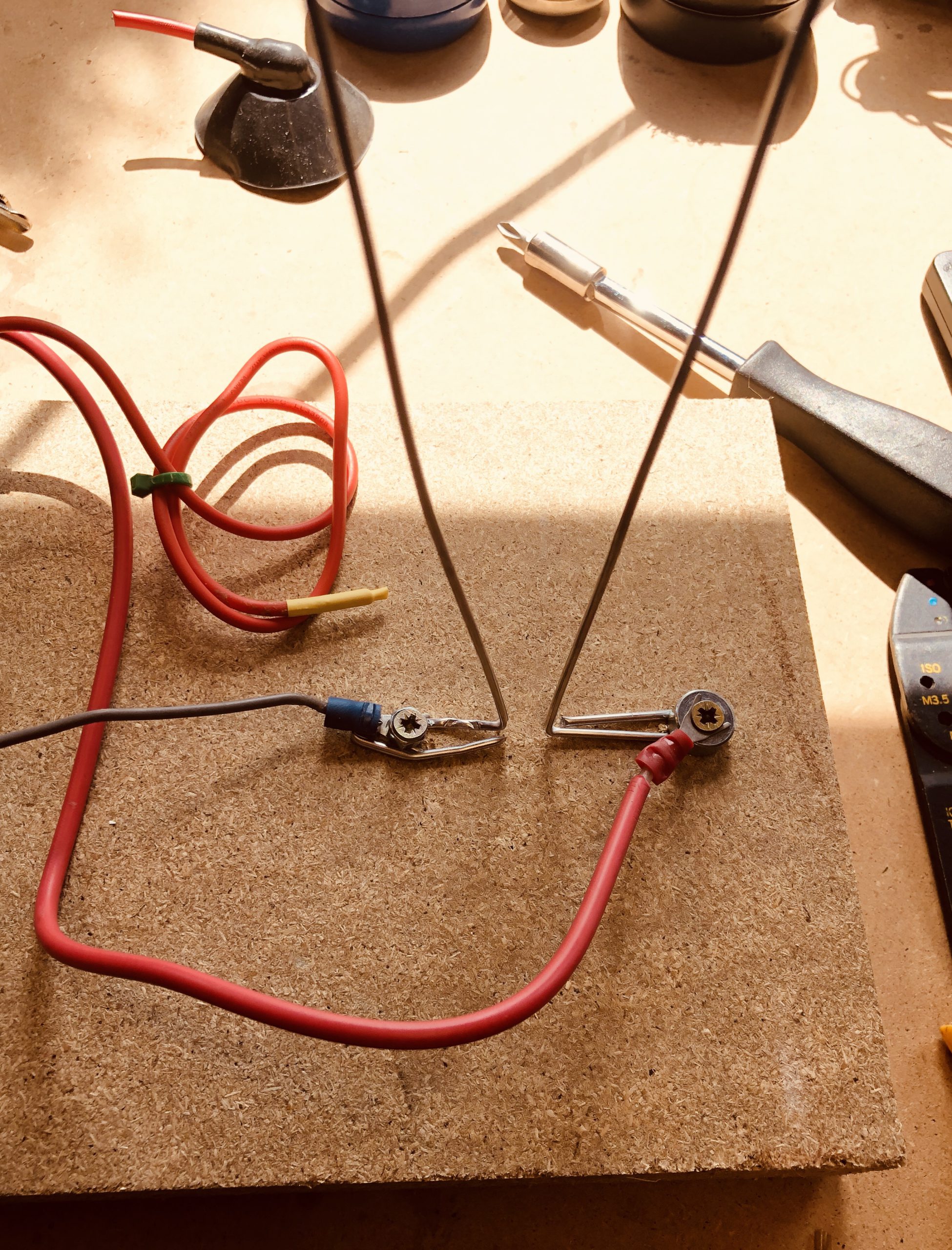
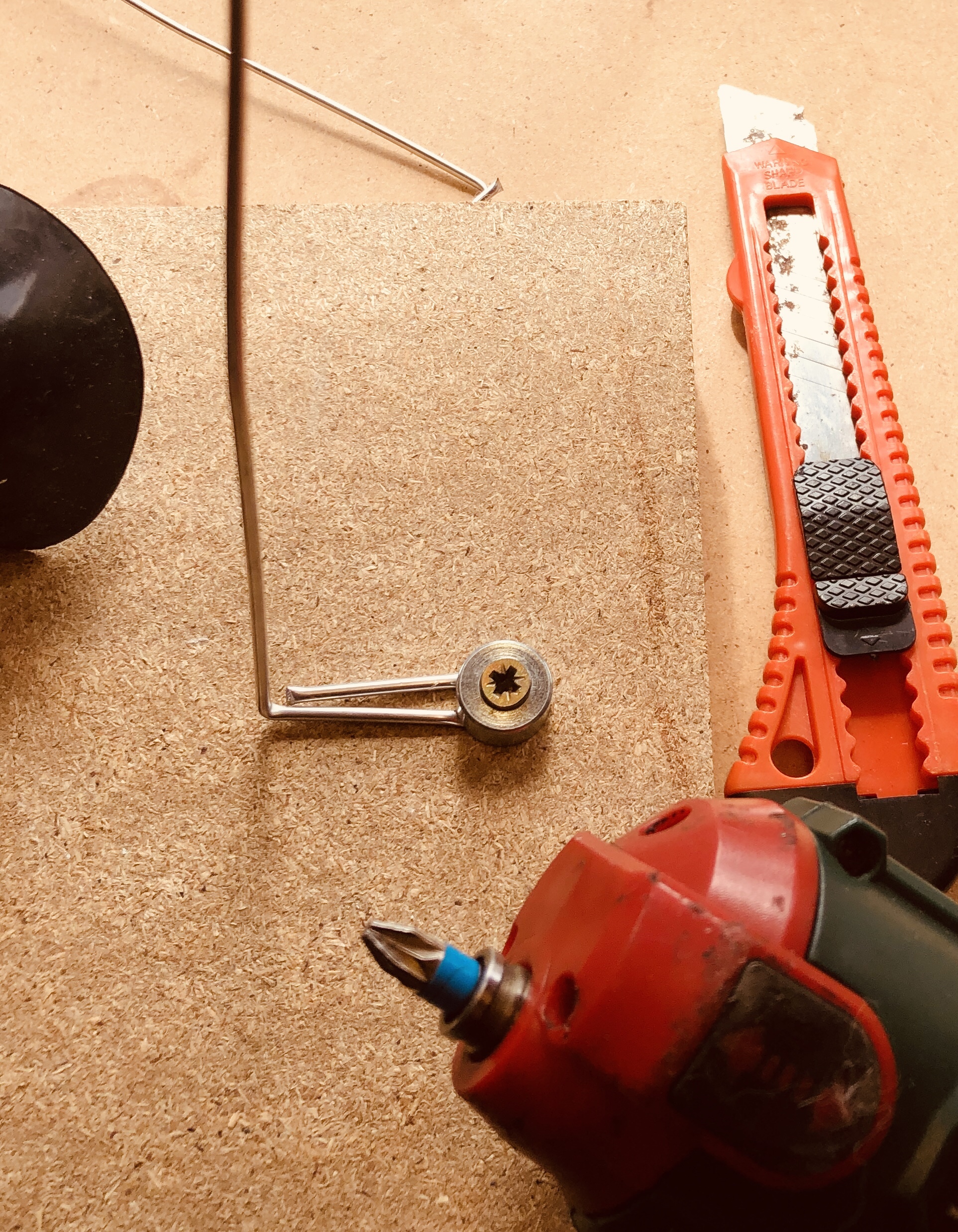
The rods were easily bent round in a U shape and bolted to the wooden platform with screws and washers. The wires from the Flyback were terminated with crimped on adaptors and screwed down between the washer and the screw.
Unsure what gap to begin testing with, we left around 3/4 inch as this seemed like a good starting point.
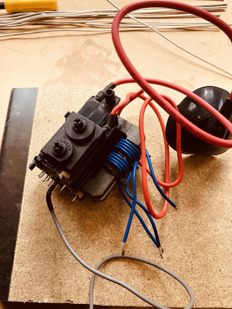
The supplied Flyback transformer had several connectors. A little googling revealed which was the ground and which of the two thick red wires provided the strongest output. Of the two wires, the thicker of the two had a small rubber cup attached to one end. This supposedly connects the Flyback to the CRT tube it was originally designed for. We snipped this off and terminated it with a crimped on spade. The other output was coiled up and the end insulated with heat shrink.
Of the many terminals on the bottom of the Flyback, one had been pre-wired with a grey wire which is the ground cable. This would be attached to one of the electrodes.
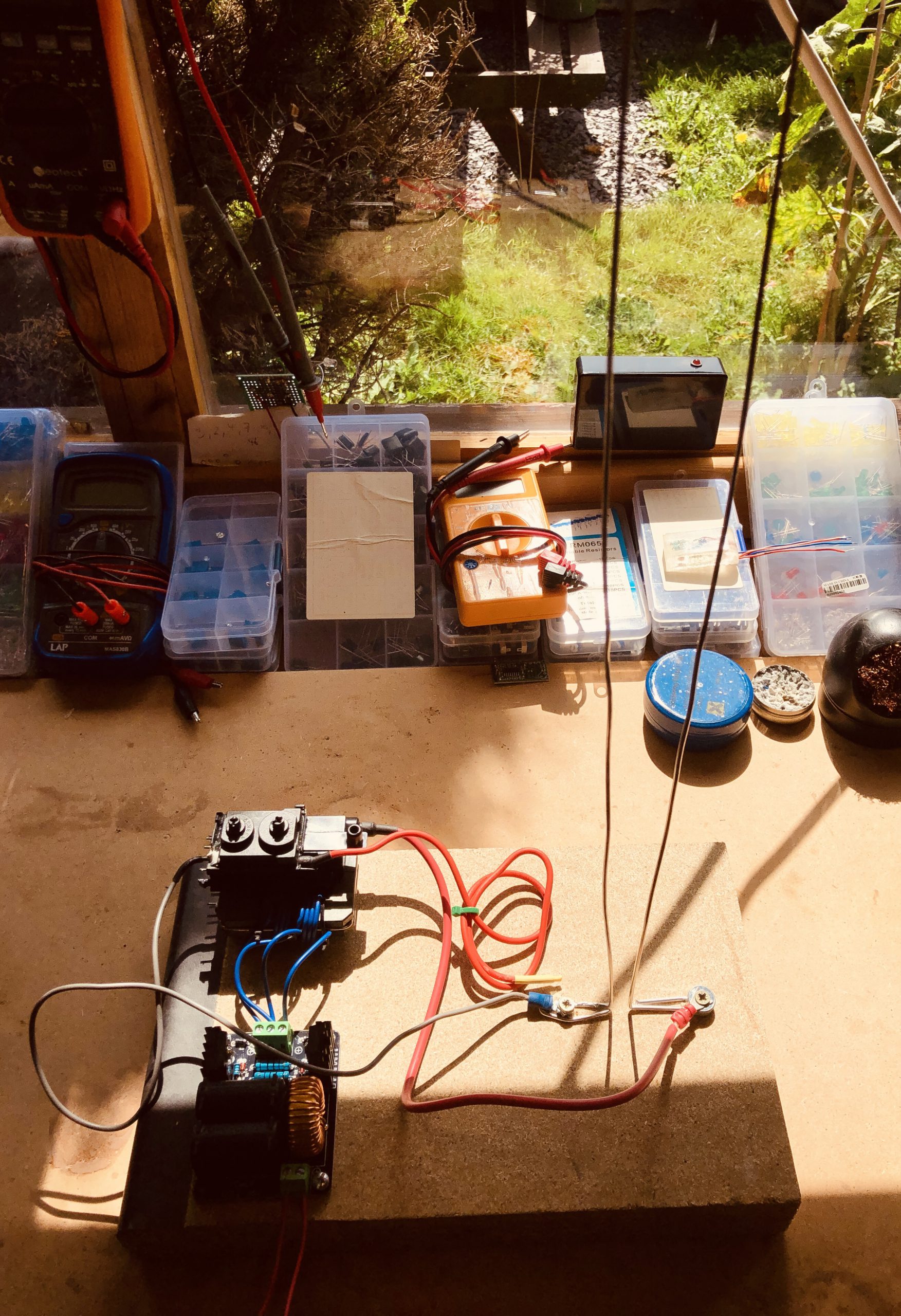
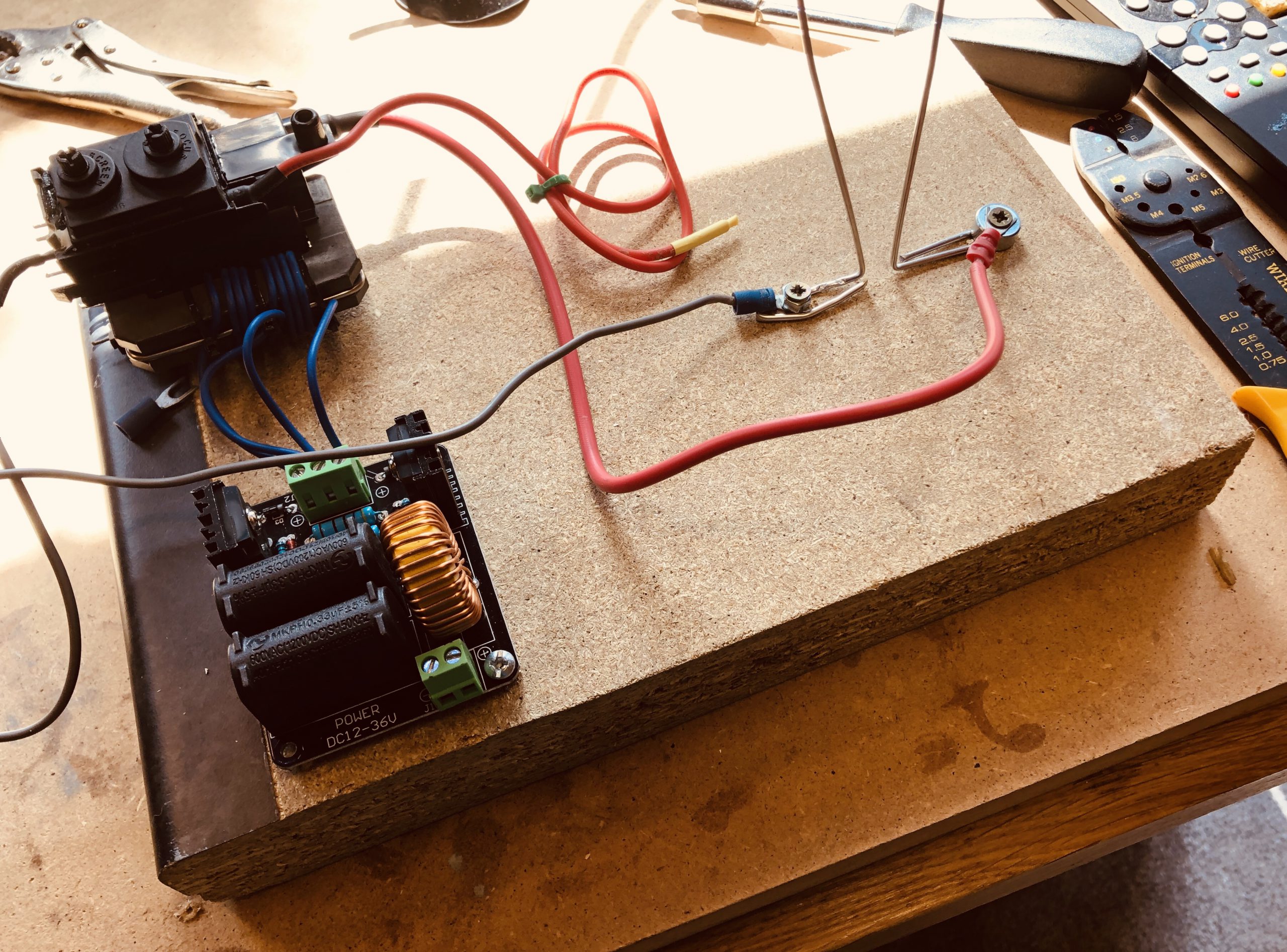
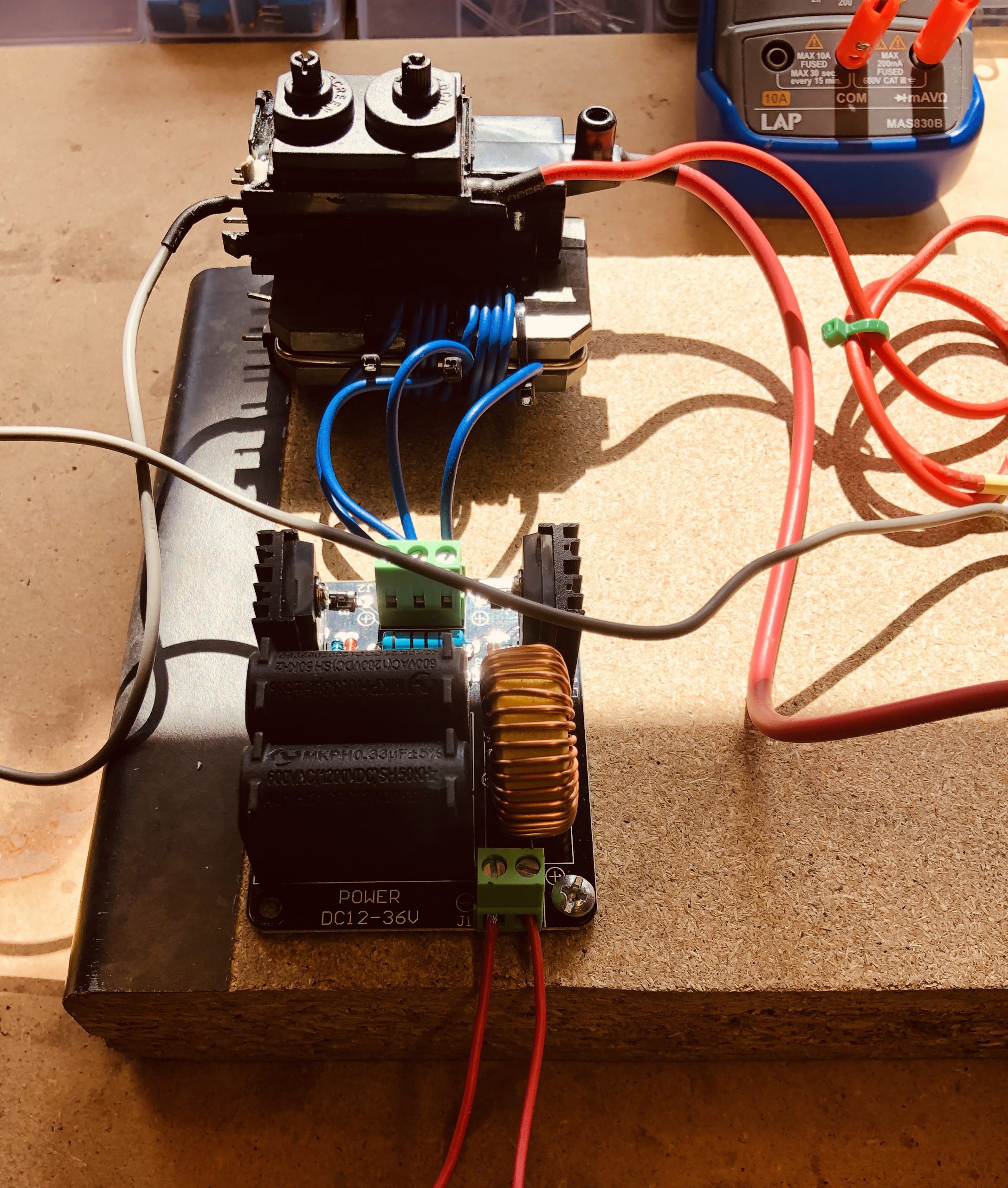
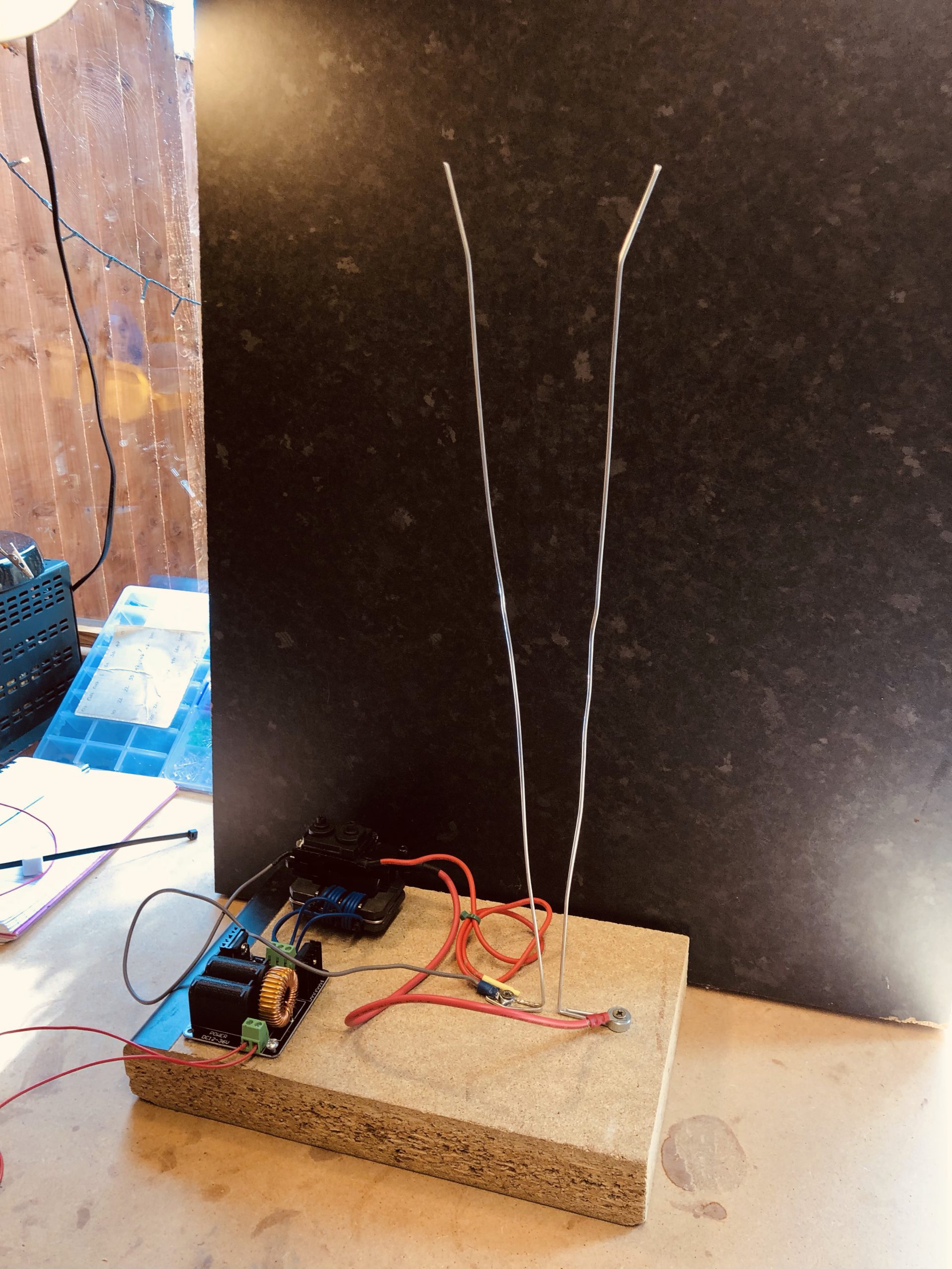
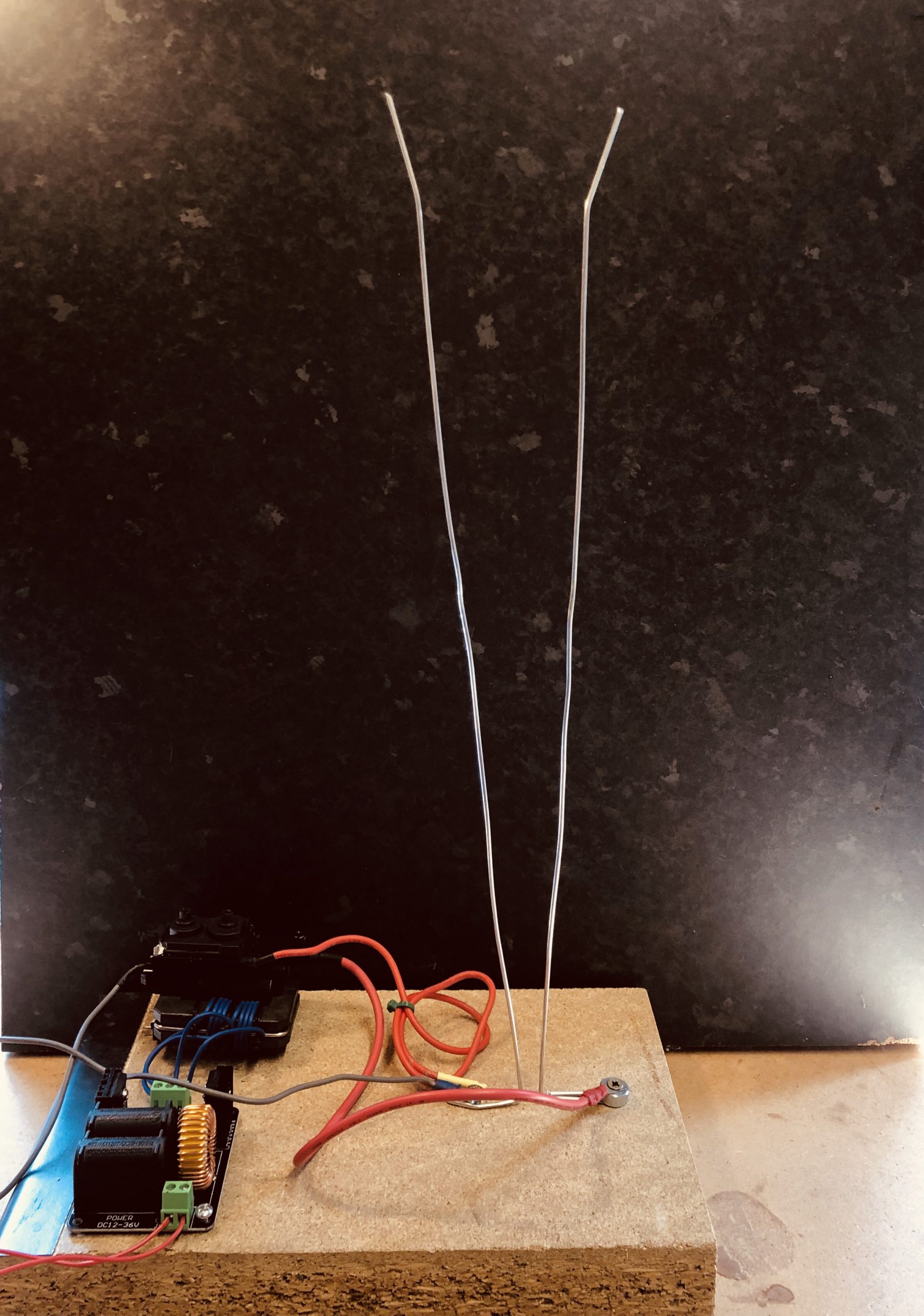
All the components were screwed to the wooden base neatly and the wires kept out of each other’s way as best as possible. The electrodes were brought up straight as possible with curved ends to ‘encourage’ the spark to dissipate as it flew off the top.
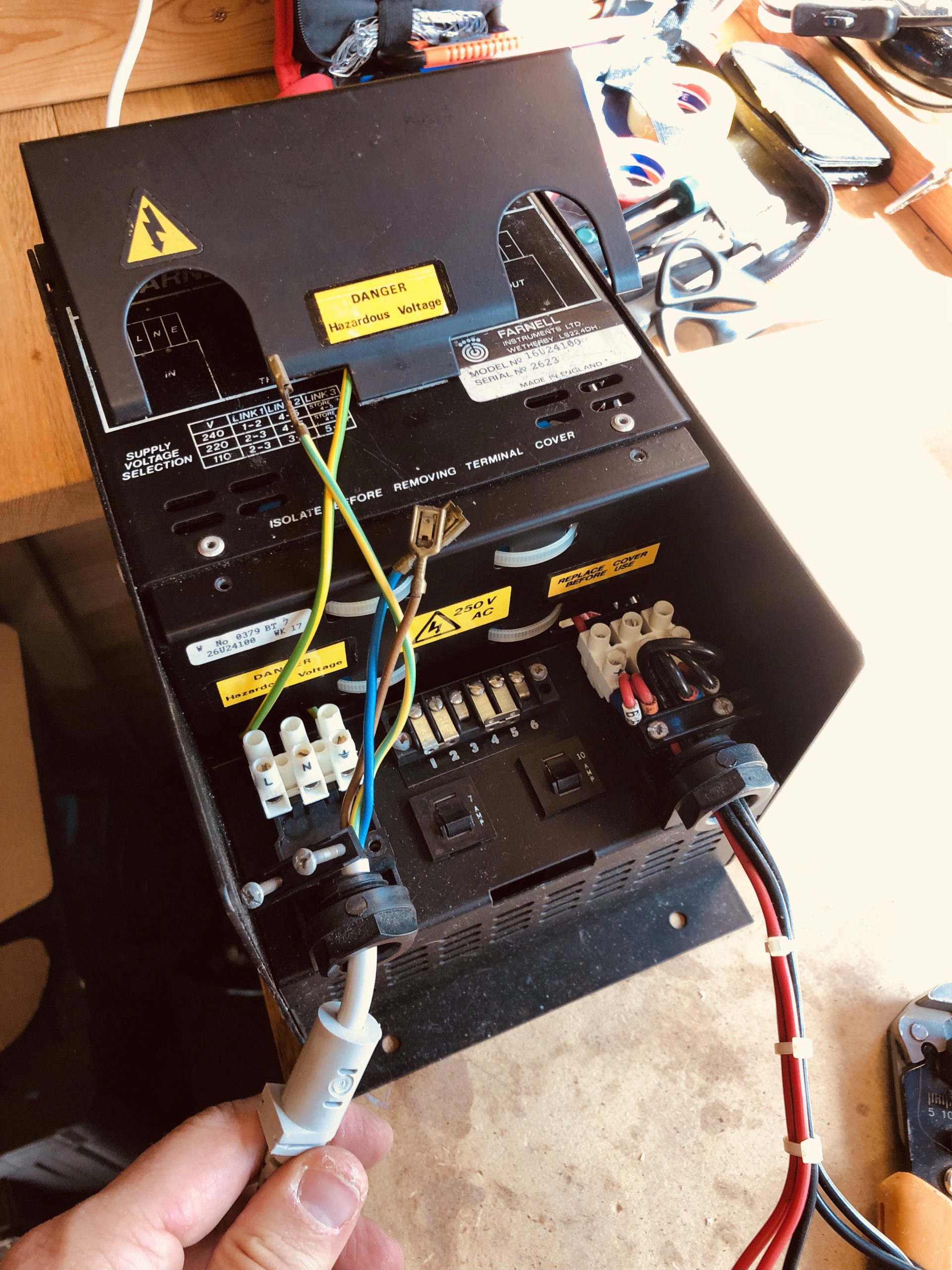
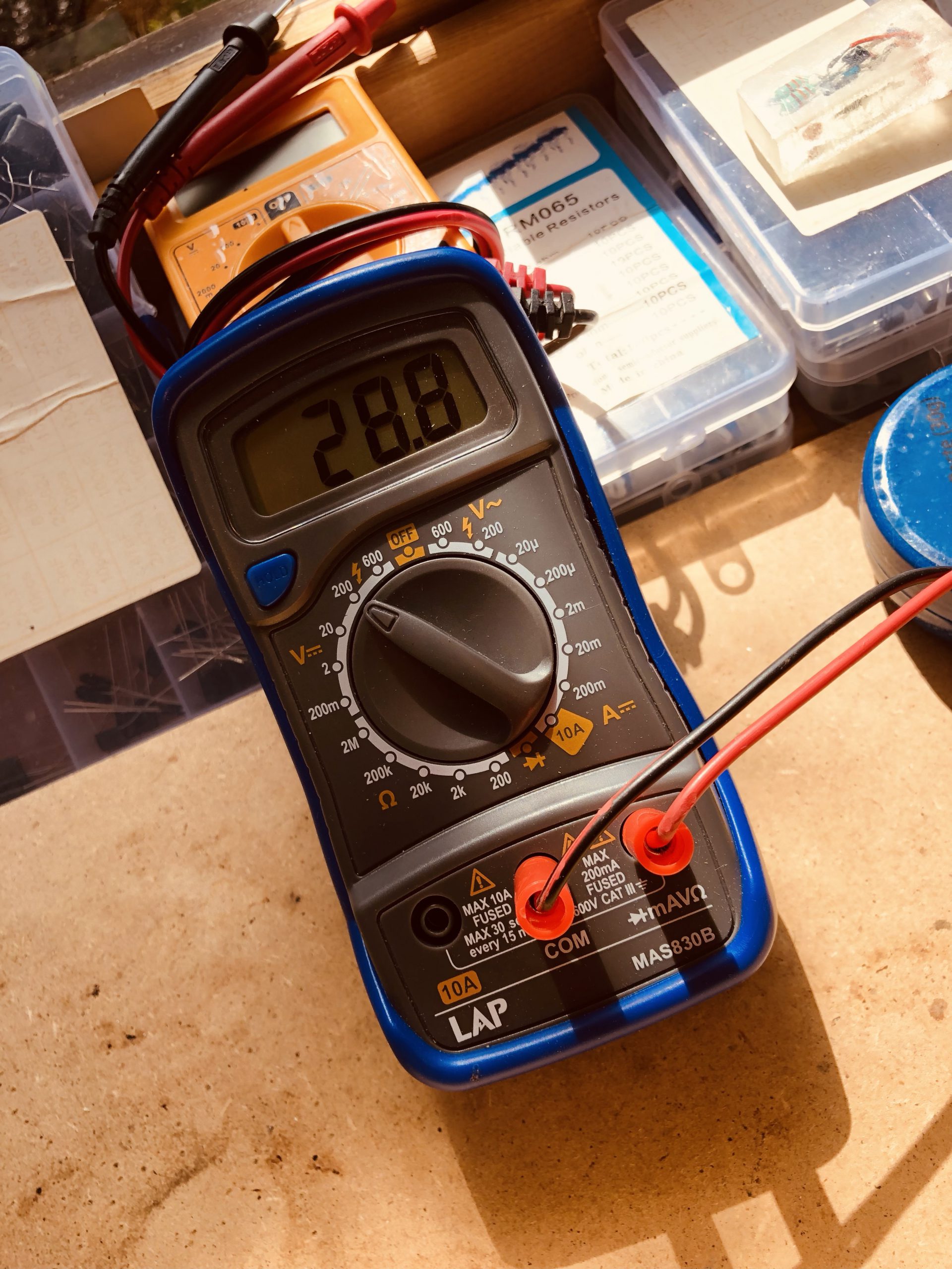
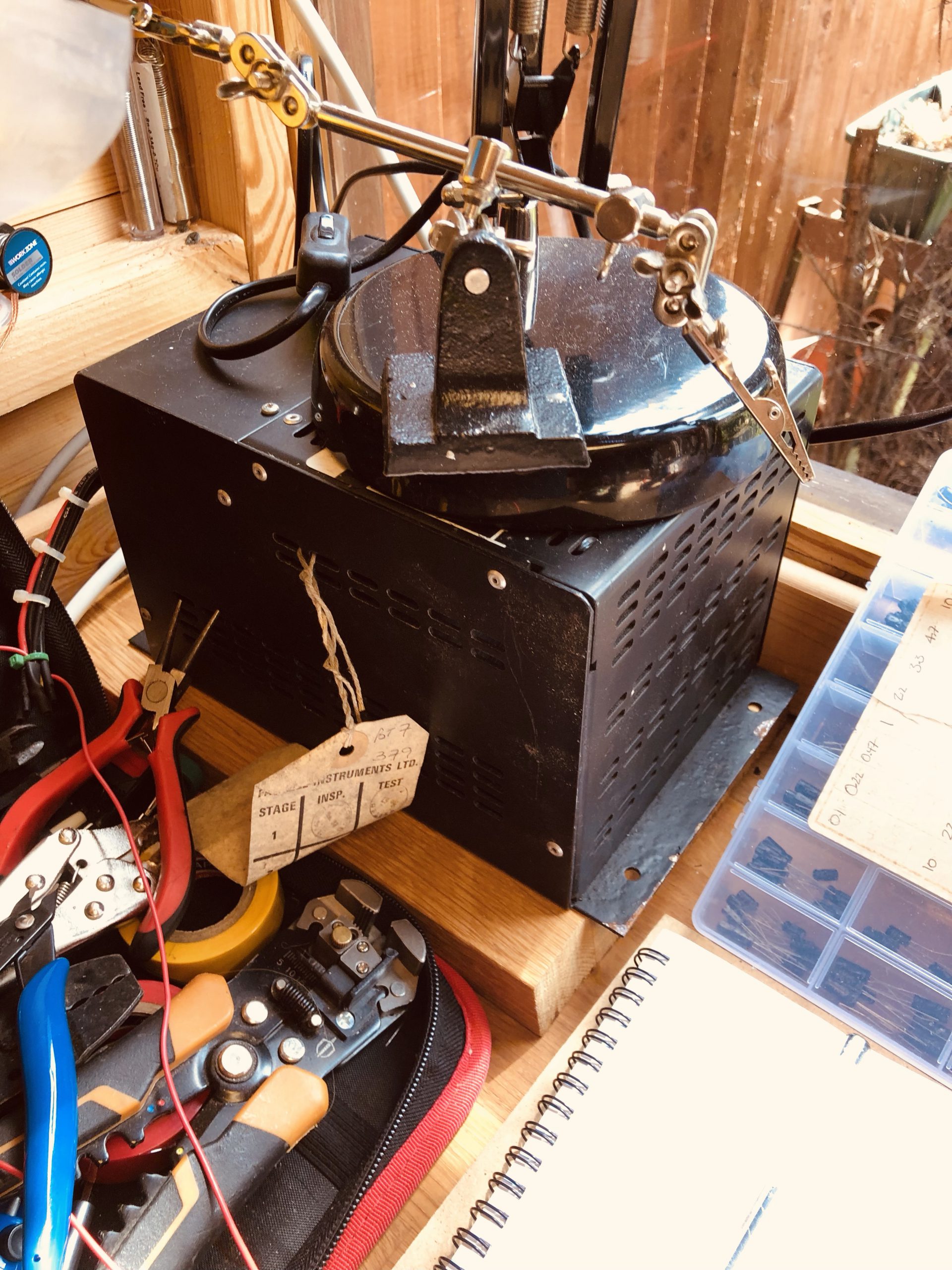
The power supply was a very old Farnell 24 volt unregulated supply that provides 10amps. The last safety test notice stated 1991, but the old PSU was still working beautifully. The supply actually output 28.8volts unloaded, and as our ZVS demands 12-36 this seemed perfect.
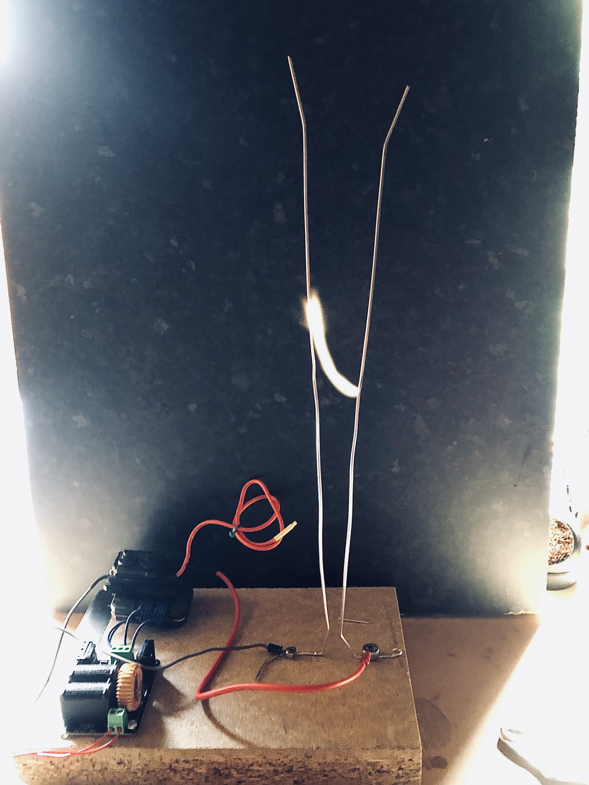
First turning the device on resulted in a arc being generated at the base of the electrodes. The arc did not rise, but a small adjustment to the electrodes gave a great improvement, seeing the arc rise dramatically up the full length of the electrodes.
The Jacobs Ladder ran well for about 3 minutes. There was a sudden cessation with no obvious cause. Adjustments to the primary coil of the Flyback resurrected the device temporarily but I suspect the secondary potted coil of the Flyback has been damaged. Testing the ZVS reveals normal working conditions, so the next step will be to replace the fly back and try and get the JL working again.
Finally, above is a short video of the Flyback rewound with thinner wire, creating a 1 inch arc between two nails.
And below: The moment it died! 🙁
Microwave Body Sensor
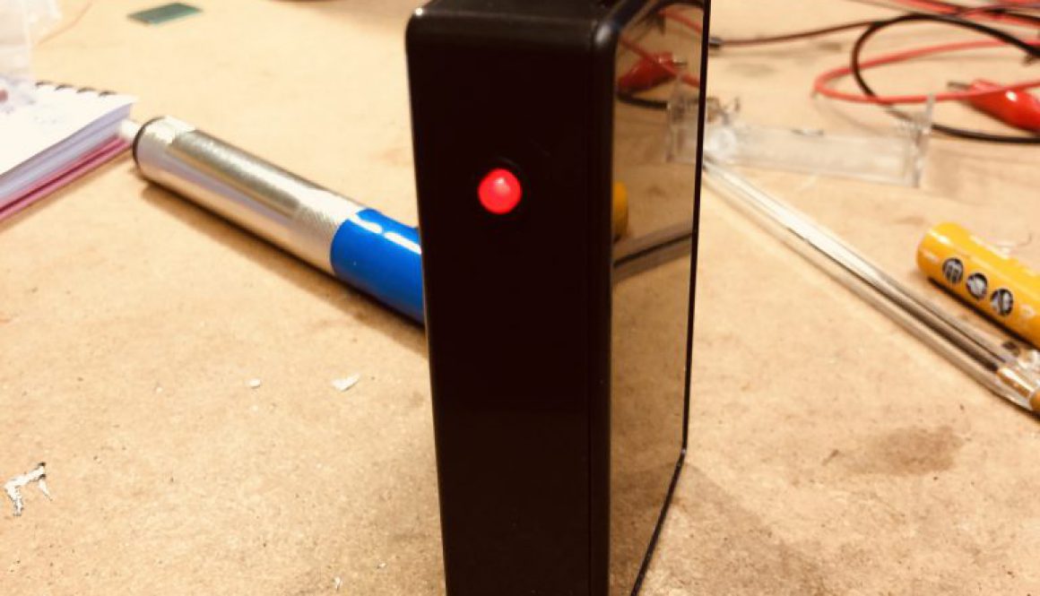
The microwave body sensor has been well documented on the internet and tested multiple times. How it works remains a mystery to many, but the set up of this device is very simple. the tiny circuit board has a regulated output, a ground, and a switched live.
When the microwave sensor detects a body within range it will power the switched live with a low current.
The unit will work approximately 20 feet away, and due to the nature of microwaves will work through walls.
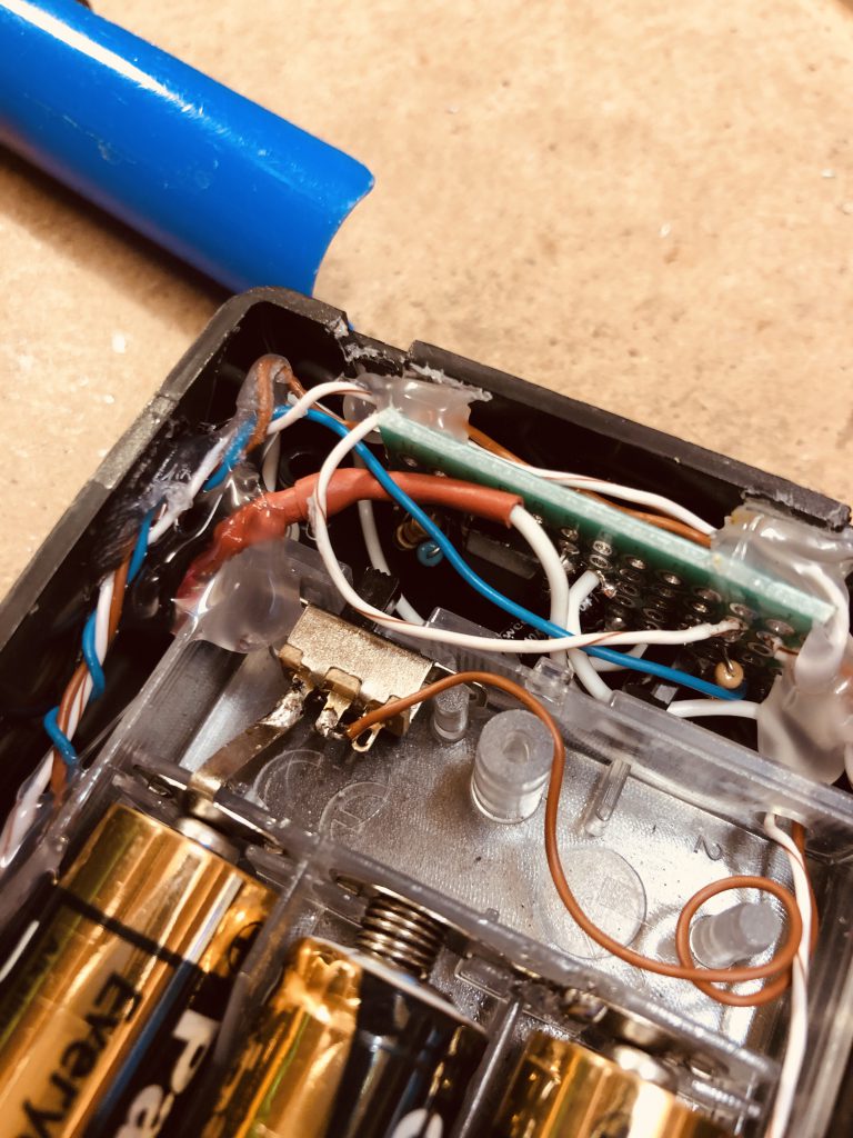
In this project the switched live powers a transistor which in turn switches on a standard 555 set up flashing a red LED.
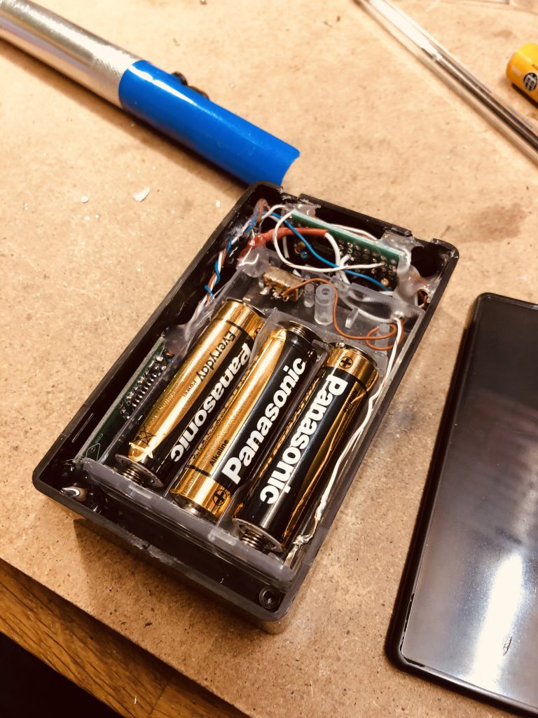
The entire project is mounted tightly into a small project box with almost the entire space occupied by 3 x AA 1.5v batteries. The microwave circuit is shoehorned down the side of the battery compartment.
In tests the microwave circuit can just about power a 555 circuit directly, but the output is brighter and sharper with a switched transistor.
This unit placed on a shelf will detect movement anywhere in the room, or the room above it.
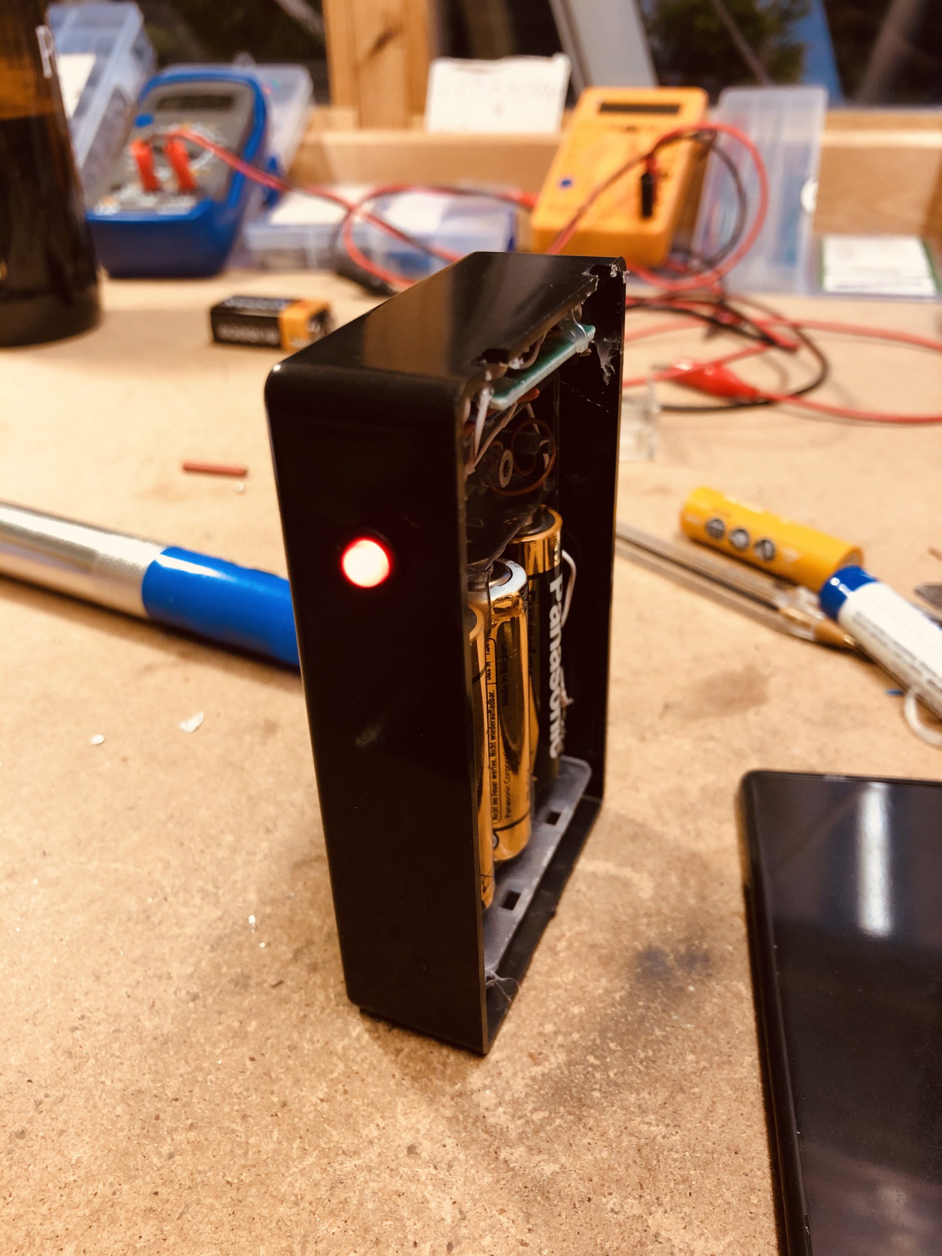
When powered up the unit takes around 5 seconds to stabilise itself during which time the output is switched on.
The Microwave sensor itself draws very little current, with the majority of the current in this circuit being drawn by the 555.
Door Lock Combination Device
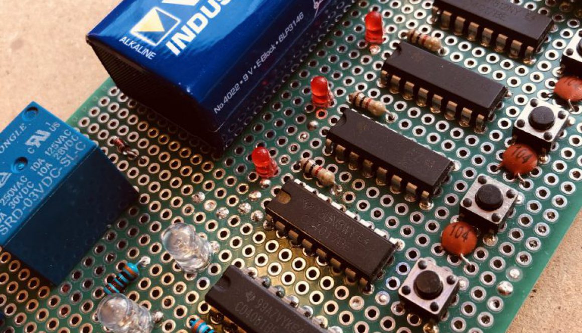
The purpose of this project was to put the 4017 to a use other than driving LEDs. The IC counts and outputs logic high signals to any number up to 10.
In this project the outputs would send 4 outputs from 4017s to a 4 input AND gate. The 4017 would be advanced manually with a push button. No LED means you must count the output of the 4017. Wiring different output pins on the 4017 essentially creates a PIN that need be known to activate all 4 outputs high at the same time.

These chosen outputs are hardwired in this project but could be user changeable with DIP switches.
When all 4 outputs are set high, the AND gate sends its own high output to the gate of a MOSFET, which in turn drives a mains relay. (And a green LED of course to show a successful code).
The only LED on the 4017s is a single small red LED that lights when the counter resets to zero, thus allowing you to know the start point.
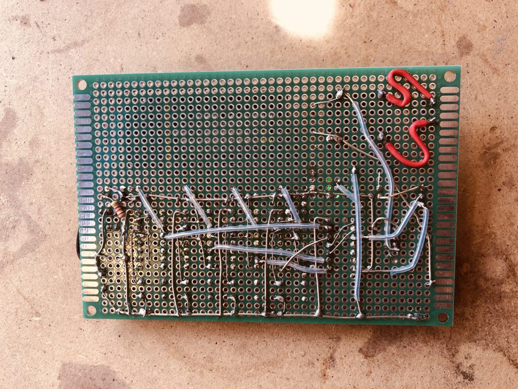
The circuit could be improved. Powering on produces random outputs on the 4017 necessitating the need to advance each 4017 to zero before you can start inputting the code.
You will also see in this project the low voltage relay is being powered by a 9v battery, and therefore causing the very low wattage resistor to get rather hot whilst protecting the relay coil.
Fitted to the inside of a door this project would be effective controlling a digital solenoid based lock and shows the versatility of the 4017 without the need for a PIC.

The SuperComputer
The project was an exercise in counting. Utilising 5 4017 ICs (of which only 4 were ever wired up) and 4 x 74LS90 ICs.
The 4017 counts sequentially from 1-10 in its purest configuration passing its tenth logic signal to its neighbouring IC as the input. In this manner the 4 processors counted to 10000. The 10000th signal was passed then to the first 74LS90.
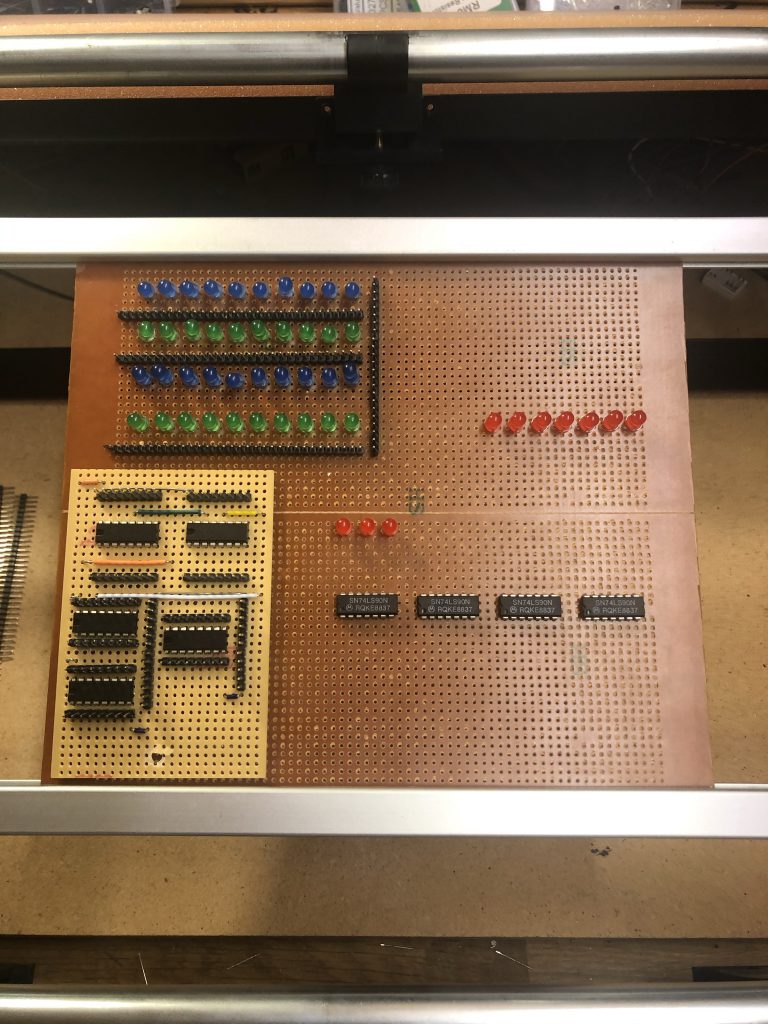
The 74LS90 is a Binary decade counter. Similar to the 4017 this IC also counts to 10 in its simplest set up however the output is in a 4bit ‘nibble’. These outputs could theoretically be connected to a decoder and then to a 7 segment LED display.
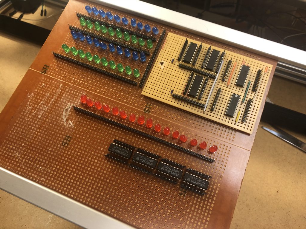
In this set up they remain in their binary output, with each 4 LEDs representing a number between 0 and 9. As with the 4017 processors, the output at the count of ten is the input of the next. The first 74LS90 is triggered by the 10000th pulse from the 4017 so accumulative the last four lights reset to 0000 when the entire computer has counted to 100,000,000.

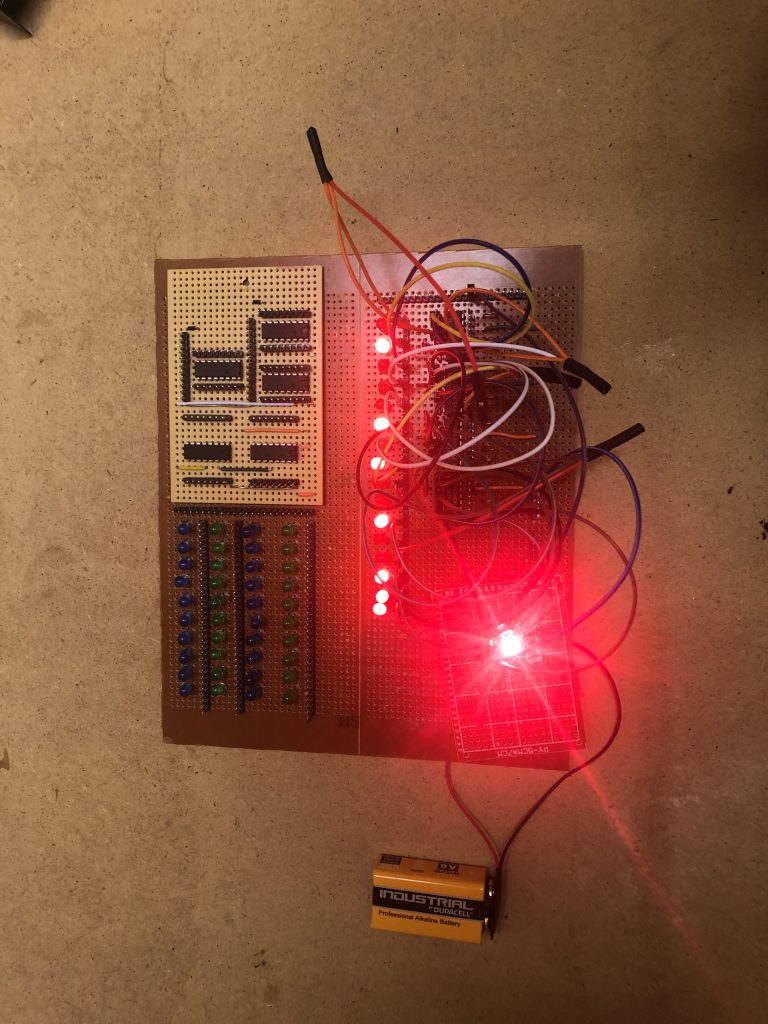
I never felt I spun this computer up to its top speed finding it difficult to obtain a fast enough initial clock pulse. Later I connected an adjustable digital variable clock output with variable duty cycle. (time on vs time off).

The Internet
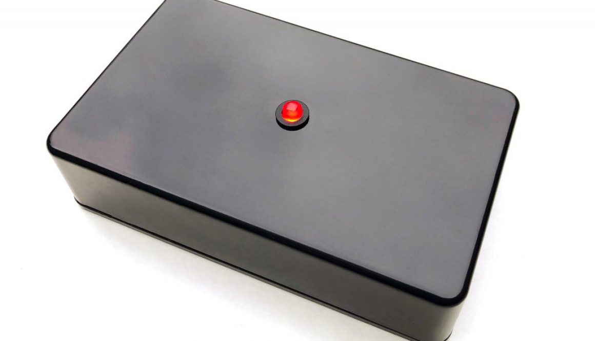
As a massive fan of the IT Crowd it made sense to create an identical replica to the box that provides the entire internet to the world. Ideally situation on the top of Big Ben (for best reception) this wireless device is to be handled with absolute care at all times. It’s a perfect talking point when giving a speech as employee of the month.
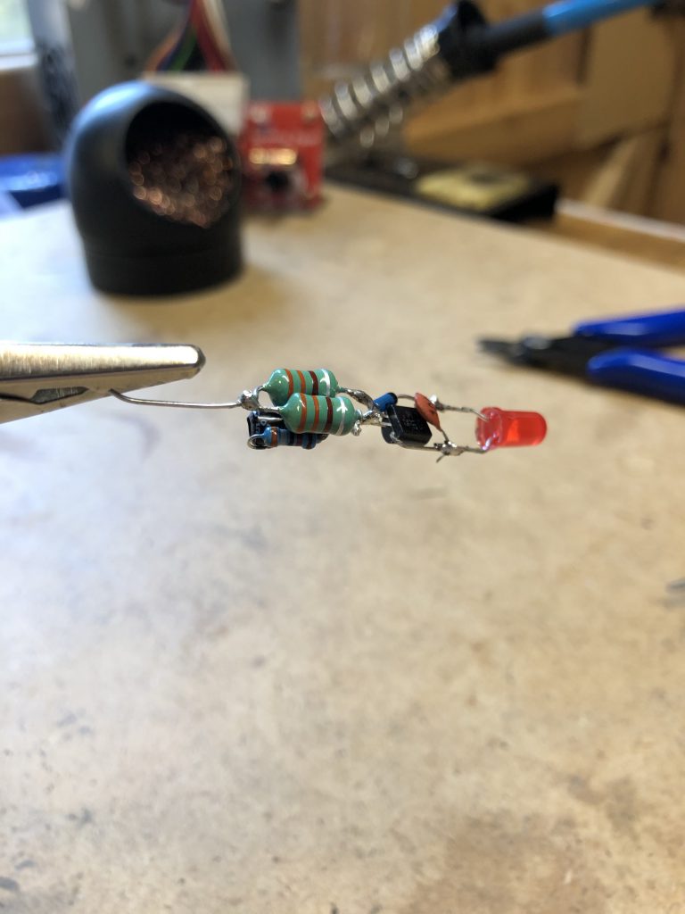
This project begins with a black box. Simply determine the centre point and drill a hole and fit an led mount. The light is a standard 5mm diffused LED.
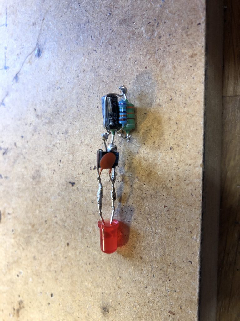
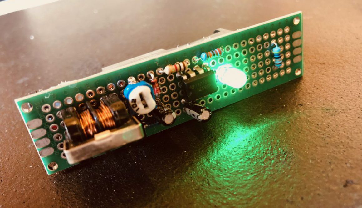
Circuitry is a little fiddly. The ideal circuit here is a high resistor, high capacitor joule thief to create a single flash around once per second. However red LEDs do not like this setup due to their low forward voltage. To create a bit more back pressure a single BAT43 diode and small cap across the output is inserted to allow the light to flash in a predictable and reliable way. Without it the light can become erratic. It is also more sensitive to bizarre behaviour as the battery voltage lowers.
The final product is a small flashing light that blinks around once per second. I estimate this should run for many many years without replacing the battery. It’s a circuit that could be used in many applications from toys to alarms.

This product will be available in kit form from the shop soon.
Digital Egg Timer
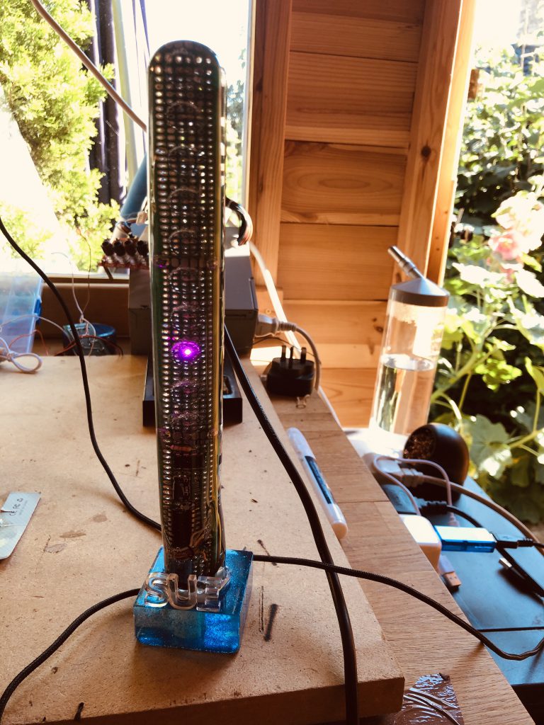
A good friend in my other life is retiring soon and needs a suitable home made present. She is passionate and putting some thought into gifts so I decided to build something electronics based and home made. A digital egg timer.
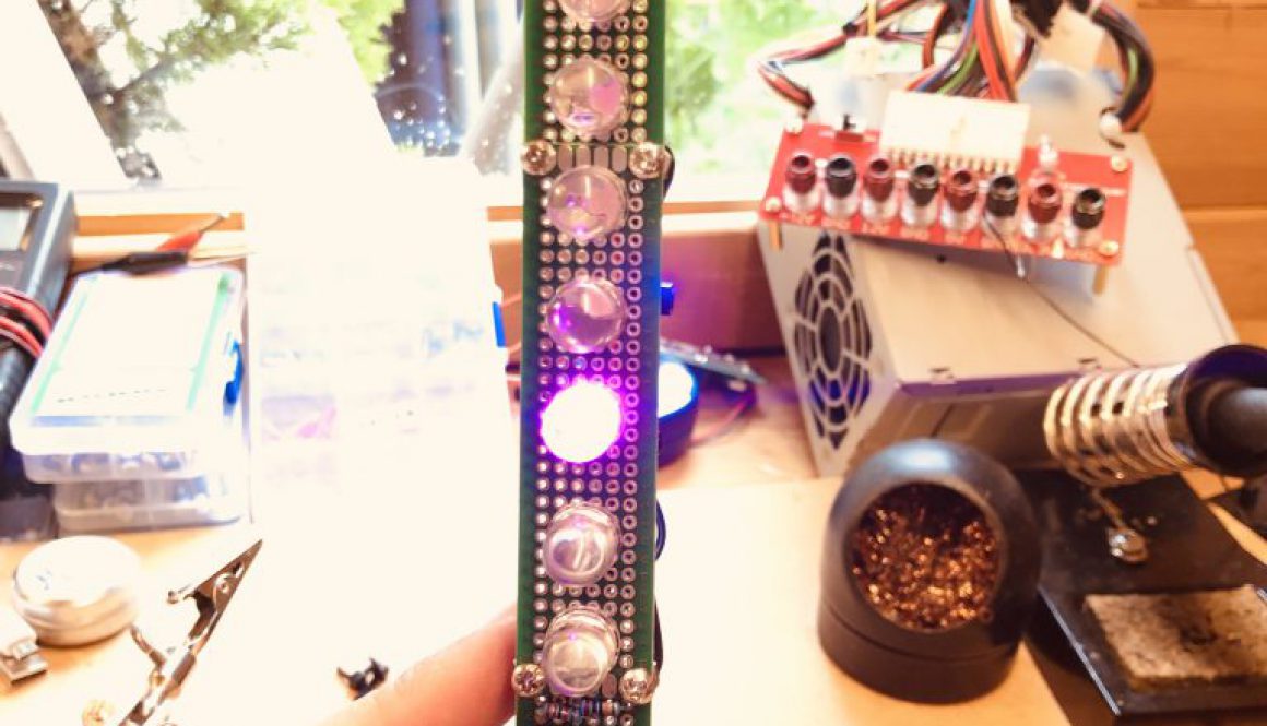
The device would be based around two electronics IC. The 555 and the 4017 counter. I asked her how long she likes to boil an egg (much to her confusion) and then configured the 555 up to trigger a signal 1/10th this time to the 4017. This then increments the pink lights until the final light shines blue. The timer then restarts. Whilst the 555 is not particularly precise in counting beyond 30 minutes, the accuracy on this 3 minute 11 second timer was pretty much spot on.
The circuit would be USB powered and use a capacitor reset circuit built on to the 4017 to inhibit random start times should the device be unplugged and plugged back in. This ensures it always starts timing from zero.
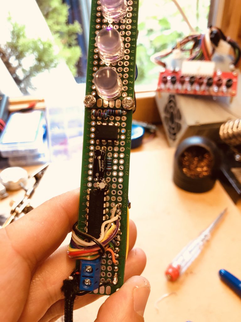
The device is built on three easily available small through-hole PCB’s which are drilled and bolted together in the corners. Resistor coded coloured wires cable each light sequentially from the 4017.
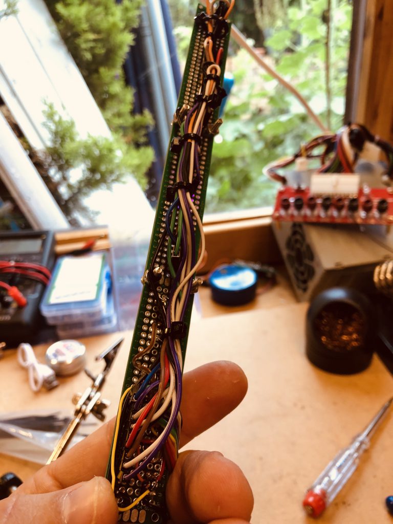
The device needed a mould and much to everyone’s amusement I chose a long thin tube which started life as a container for bubble fluid. The tube was cut and the circuit carefully held in on a clamp. This was then filled with high quality two part epoxy.
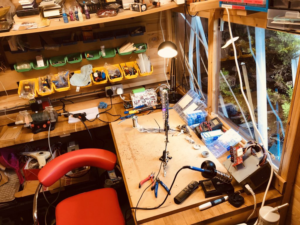
A test run on a separate tube caused the tube to distort due to the heat when hardening, so on this project the epoxy was added in stages.
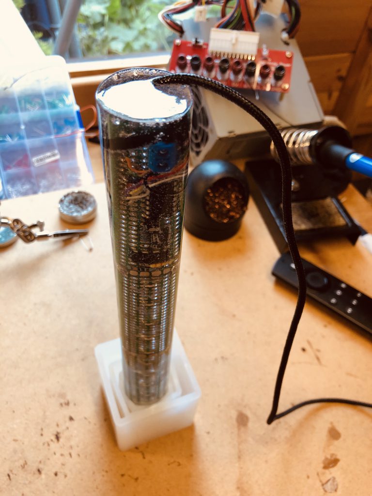
After hardening a suitable base was made (also from epoxy) and lettered with more epoxy and the usb cable run out the back.

The finished product.