Door Lock Combination Device
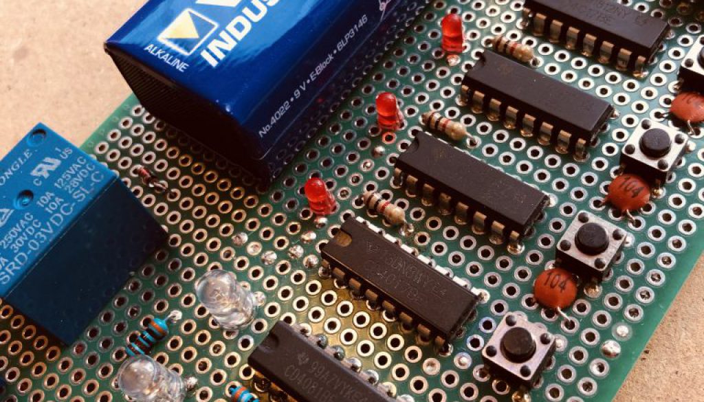
The purpose of this project was to put the 4017 to a use other than driving LEDs. The IC counts and outputs logic high signals to any number up to 10.
In this project the outputs would send 4 outputs from 4017s to a 4 input AND gate. The 4017 would be advanced manually with a push button. No LED means you must count the output of the 4017. Wiring different output pins on the 4017 essentially creates a PIN that need be known to activate all 4 outputs high at the same time.

These chosen outputs are hardwired in this project but could be user changeable with DIP switches.
When all 4 outputs are set high, the AND gate sends its own high output to the gate of a MOSFET, which in turn drives a mains relay. (And a green LED of course to show a successful code).
The only LED on the 4017s is a single small red LED that lights when the counter resets to zero, thus allowing you to know the start point.
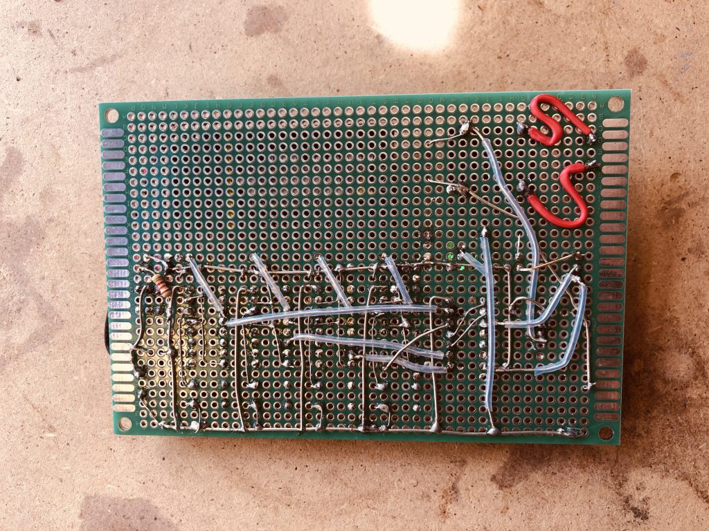
The circuit could be improved. Powering on produces random outputs on the 4017 necessitating the need to advance each 4017 to zero before you can start inputting the code.
You will also see in this project the low voltage relay is being powered by a 9v battery, and therefore causing the very low wattage resistor to get rather hot whilst protecting the relay coil.
Fitted to the inside of a door this project would be effective controlling a digital solenoid based lock and shows the versatility of the 4017 without the need for a PIC.
